Various inlet manifolds

General Chat About Exhaust, Cylinder Heads, Fuel Systems And Intake

Moderator: phpBB2 - Administrators

DaveEFI
Gold Member
Gold Member
Posts: 4603
Joined: Fri Feb 26, 2010 4:27 pm
Location: SW London, UK

Various inlet manifolds

Post by DaveEFI »

I'm in the process of changing my MegaSquirt standard Vitesse engine to sequential injection.

On the principle of doing one thing at a time, I was hoping to first change to hotwire high impedance injectors as the Vitesse low impedance ones cant be used with the later MS injector drivers, without also using resistors, which I got rid of. And get a reasonable tune with them on batch injection before changing the wiring loom, etc, and going sequential. Also going the change the fast idle arrangements.

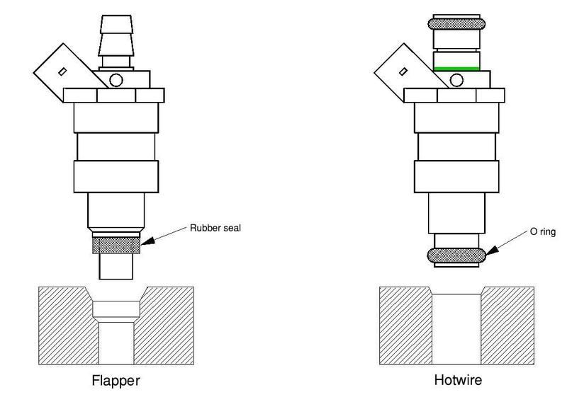
I hadn't noticed that the injector holes in the manifold are different between the two types, as well as the fuel rail. And that the later fuel rail fouls the CTS on the flapper manifold.

So it looks like it is going to be easier to change the manifold as it would have to come off anyway to modify the injector holes.

I have four different assorted ones here. :D

Looks to be like a Gems one may be the best bet - it has a heater feed which the hotwire doesn't, and should be quite easy to plumb in. My Vitesse heater feed comes from the back of the thermostat housing and runs underneath the manifold. A PITA if it leaks.

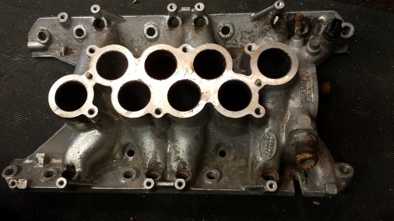
This is a pic of the one I'm intending using - I think it is Gems.

Image

It had no thermostat in the usual place - but looks like one can be fitted using the SD1 elbow.

Any obvious gotchas I'm missing? Are the internal waterways the same?


Dave
London SW
Rover SD1 VDP EFI
MegaSquirt2 V3
EDIS8
Tech Edge 2Y
kiwicar
Forum Contributor
Forum Contributor
Posts: 5461
Joined: Sat Nov 18, 2006 5:00 pm
Location: Milton Keynes

Post by kiwicar »

Hi
Is there one with straighter runners? They seem unusually twisty, especially the one bottom left. Wouldn't a 4 barrel open plenum manifold with a 4 barrel throttle plate and the runners tapped for the injectors not give you a neater solution? Or are you after a "factory" look?
best regards
Mike
poppet valves rule!
DaveEFI
Gold Member
Gold Member
Posts: 4603
Joined: Fri Feb 26, 2010 4:27 pm
Location: SW London, UK

Post by DaveEFI »

That part of it looks to be the same as the original Vitesse one.

I'm not looking to change things much as the present set-up works well enough. Really just to see the difference between batch and sequential - and upgrade the original fast idle method. The Vitesse injection was pretty early. :D
Dave
London SW
Rover SD1 VDP EFI
MegaSquirt2 V3
EDIS8
Tech Edge 2Y
User avatar
ChrisJC
Top Dog
Top Dog
Posts: 5077
Joined: Mon Nov 20, 2006 1:13 pm
Location: Northants / Cambs
Contact:

Post by ChrisJC »

It should be fine. I have heard this idea of fitting a thermostat before, but I have never actually seen it done. So it will be interesting to see.

The internal water paths are the same as far as I know.

The Thor manifold changed around the plumbing (to get longer inlets I think), but GEMS and EFi are the same.

Good luck!

Chris.
--
Series IIA 4.6 V8
R/R P38 4.6 V8
R/R L405 4.4 SDV8
DaveEFI
Gold Member
Gold Member
Posts: 4603
Joined: Fri Feb 26, 2010 4:27 pm
Location: SW London, UK

Post by DaveEFI »

I've got a Thor manifold too. It is very different. All the others at least look to be interchangeable with the trumpet bases and plenums - but not the Thor.

It looks to have more regular shaped tracts then the older one - but the extra length really comes from the top part.
Dave
London SW
Rover SD1 VDP EFI
MegaSquirt2 V3
EDIS8
Tech Edge 2Y
SuperV8
Guru
Guru
Posts: 982
Joined: Tue Jul 07, 2009 11:25 pm
Location: West midlands

Post by SuperV8 »

Which part of the hotwire fuel rail fouls the flapper manifold?
If its the fuel temp sensor boss then just cut it off as not needed with MS. I cut mine off and filed flat and you can't tell it was ever there.
I fitted bosch later type injectors to the flapper manifold and worked ok although I think it could have done with better seals where the injectors fit into the manifold so using the later manifold is a better job.
I'm now using the GEMS manifold and using a remote thermostat in the pump inlet (from a freelander) similar to the GEMS setup but with a lower stat opening temp.


Tom.
Dax Rush 4.6 supercharged V8 MSII
Quagmire
Knows His Stuff
Knows His Stuff
Posts: 377
Joined: Wed Jul 30, 2008 9:42 am
Location: Hook, UK

Post by Quagmire »

I have this exact manifold on my landrover - and did that same thing as you, i.e. it replaced a working flapper top end so I could use later injectors.

All works fine with thermostat in usual place. :D

Heres my thread asking about plumbing at the time:

http://www.v8forum.co.uk/forum/viewtopic.php?t=10969
1974 Rover 3500s
1984 3.5 90
1959 2.25 series 2
DaveEFI
Gold Member
Gold Member
Posts: 4603
Joined: Fri Feb 26, 2010 4:27 pm
Location: SW London, UK

Post by DaveEFI »

The hotwire fuel rail fouls the CTS connector on the flapper manifold.
You might get away with fitting the connector first, then the rail, but I'd rather not. On the hotwire manifold, the CTS is moved to where the thermotime switch is on the flapper - but the threads are different.

As regards the seals between injector and manifold, this might explain things.

Image

I was originally hoping to simply fit the hotwire injectors with a minimum amount of dismantling. But since it's not that easy, I might as well do it properly - or at least as best I can.
Dave
London SW
Rover SD1 VDP EFI
MegaSquirt2 V3
EDIS8
Tech Edge 2Y
SuperV8
Guru
Guru
Posts: 982
Joined: Tue Jul 07, 2009 11:25 pm
Location: West midlands

Post by SuperV8 »

Looking back through my photo's trying to see my temp sensor. This is the best photo I have, using the coolant temp sensor which I got with my coolant temp gauge and I can unplug it with the fuel rail in place, close but ok.
Image

I agree better to use the correct manifold for the o-ringed injectors but when I used the o-ringed injectors on the flapper manifold it did see to work ok, no obvious leaks on vacuum and idled well, although I had a suspicion under boost it leaked although I was never able to prove it.

Tom.
Dax Rush 4.6 supercharged V8 MSII
DaveEFI
Gold Member
Gold Member
Posts: 4603
Joined: Fri Feb 26, 2010 4:27 pm
Location: SW London, UK

Post by DaveEFI »

Tom, it's the CTS for the injection which fouls the hotwire fuel rail on a flapper manifold.

I've yet to work out what I'll do with the sensor for the dash temperature gauge - there's no dedicated place for it on the Gems manifold.

Why is nothing ever easy? :D
Dave
London SW
Rover SD1 VDP EFI
MegaSquirt2 V3
EDIS8
Tech Edge 2Y
User avatar
Eliot
Top Dog
Top Dog
Posts: 1765
Joined: Sat Nov 18, 2006 9:46 am
Location: Milton Keynes
Contact:

Post by Eliot »

kiwicar wrote:Hi
Is there one with straighter runners? They seem unusually twisty, especially the one bottom left. Mike
Mike - the bottom left runner is fed by the "hole" opposite (top left). The bottom Left "hole" feeds the top left runner.
Eliot Mansfield
5.7 Dakar 4x4, 4.6 P38 & L322 TDV8
www.mez.co.uk / www.efilive.co.uk
stevieturbo
Forum Contributor
Forum Contributor
Posts: 4054
Joined: Sat Nov 18, 2006 6:22 pm
Location: Northern Ireland

Post by stevieturbo »

Just drill out the old manifold to suit the 14mm injectors.


And if you're looking to see difference between batch and sequential....but you're also changing intake, injectors and other stuff ?

It really isnt going to be a valid test with so many changes.

But the real answer is, there will barely be any difference from the batch to sequential change alone, although it would allow you to play with injection timing if you really wanted to push for economy.
9.85 @ 144.75mph
202mph standing mile
http://www.youtube.com/watch?v=XgWRCDtiTQ0
DaveEFI
Gold Member
Gold Member
Posts: 4603
Joined: Fri Feb 26, 2010 4:27 pm
Location: SW London, UK

Post by DaveEFI »

I was hoping initially to just fit the different injectors.

To drill out the old manifold would mean removing it. I'd also have to modify the threads for the thermotime unit to fit the CTS where it goes, to clear the fuel rail.

I can't use the original injectors. They are low impedance and I'm driving them PVM in batch. MS3x injector drivers can't drive low impedance injectors without using series resistors. Which IMHO would be retrograde step.

My intention was the change to the new injectors and get a decent tune with those, staying with MS2. Then change to MS3 and sequential. Which should show just the difference.

Other thing is I'd be delighted to use a better manifold than the flapper one on the SD1. It has a steel heater pipe running underneath it. If that leaks (I've had a couple which have) it's a major job to change.

I already have spare flapper, hotwire, gems (and Thor :D ) manifolds, so it's really just a question of using the best one for my eventual setup. For the coolant plumbing as well as injection.
Dave
London SW
Rover SD1 VDP EFI
MegaSquirt2 V3
EDIS8
Tech Edge 2Y
stevieturbo
Forum Contributor
Forum Contributor
Posts: 4054
Joined: Sat Nov 18, 2006 6:22 pm
Location: Northern Ireland

Post by stevieturbo »

Whilst I wouldnt be fond of using resistors myself.

Quite a few OEM's do it this way. So there must be some reason behind it, and it cant be as bad as you'd think.

Quite a few Hondas, Toyotas, Mitsi Evo's etc to name a few all use resistor packs and low impedance injectors.

Seems strange they'd do it if it was bad....but you'd think it a lot easier to run without resistors !
9.85 @ 144.75mph
202mph standing mile
http://www.youtube.com/watch?v=XgWRCDtiTQ0
DaveEFI
Gold Member
Gold Member
Posts: 4603
Joined: Fri Feb 26, 2010 4:27 pm
Location: SW London, UK

Post by DaveEFI »

stevieturbo wrote:Whilst I wouldnt be fond of using resistors myself.

Quite a few OEM's do it this way. So there must be some reason behind it, and it cant be as bad as you'd think.

Quite a few Hondas, Toyotas, Mitsi Evo's etc to name a few all use resistor packs and low impedance injectors.

Seems strange they'd do it if it was bad....but you'd think it a lot easier to run without resistors !
They had no real option in the early days as injectors then were basically low impedance. And electronics too crude to use PWM. We are talking about 30 odd years ago when most things were analogue. These days processing power costs pennies.

Easy enough to see why adding a resistor isn't ideal. Try it with any sort of motor. It reduces the maximum torque. Using PMW doesn't.
So the theory is an injector driven direct will react to a command from the driver quicker and more faithfully. Basically, any form of electric 'motor' gives its best when fed from a low impedance source.

Also. flapper injectors were early in the scheme of things. Later ones *should* be of a better design in more than one way.

Not having resistors also simplifies the loom design somewhat. So can't think of any reason to use them, unless forced to. Which doesn't apply here. :D
Dave
London SW
Rover SD1 VDP EFI
MegaSquirt2 V3
EDIS8
Tech Edge 2Y
Post Reply

Return to “Exhaust, Cylinder Heads, Fuel And Intake Area”