EDIS coil

General Chat About Electrics, And Ignition Systems.

Moderator: phpBB2 - Administrators

Post Reply
DaveEFI
Gold Member
Gold Member
Posts: 4603
Joined: Fri Feb 26, 2010 4:27 pm
Location: SW London, UK

EDIS coil

Post by DaveEFI »

Just discovered I don't really know for sure how an EDIS coil works.

The primary side is fairly obvious - current flows between +12v and ground, when it is 'turned' on.

But there is no continuity between plug outputs to ground, so I've sort of assuming current is induced into the secondary winding which then flows from one plug to the other on the same circuit? Measuring between both plug outputs on one coil shows a resistance of approx 12,000 ohms. Can't really get my head round current flowing between two grounds. :D


Dave
London SW
Rover SD1 VDP EFI
MegaSquirt2 V3
EDIS8
Tech Edge 2Y
DEVONMAN
Top Dog
Top Dog
Posts: 1440
Joined: Sat Dec 13, 2008 2:46 pm
Location: Croydon UK

Post by DEVONMAN »

I believe the flow is from one plug to the other and I thing the spark jumps from centre to body on one plug and from body to centre on the other.


Years ago we used to check if the coil was connected the right way round by watching the spark jump on the plug. If it jumped from the body to the centre electrode then it needed to be swapped over to get what was then considered the best spark. If on the edis coils one spark jumps from body to centre then the old theory goes out the window.


Regards Denis
1950 A40 Devon Hotrod with 5.0 twin turbo RV8.
EDIS8 wasted spark, Holley Injection.
Been as far as the Moon and back in 57 years of driving. Same Car, 5 engine upgrades !!!


Image
User avatar
ChrisJC
Top Dog
Top Dog
Posts: 5077
Joined: Mon Nov 20, 2006 1:13 pm
Location: Northants / Cambs
Contact:

Post by ChrisJC »

I am pretty sure that is correct.

Chris.
--
Series IIA 4.6 V8
R/R P38 4.6 V8
R/R L405 4.4 SDV8
Cobratone
Is a Spanner
Posts: 313
Joined: Thu Jan 08, 2009 7:43 pm
Location: East Mids
Contact:

Post by Cobratone »

Is this article any use to you??

http://www.dainst.com/info/edis/edis.html
SuperV8
Guru
Guru
Posts: 982
Joined: Tue Jul 07, 2009 11:25 pm
Location: West midlands

Post by SuperV8 »

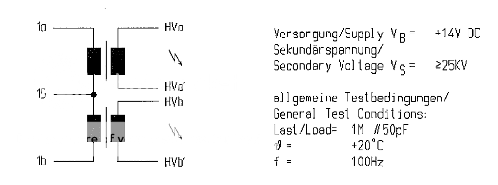
This is the wiring for an Edis coil, which is no different to most other coil packs.

Image

The secondary windings are not connected, just the primary windings via live, with separate switched earths.
Each secondary winding has two outputs
The plug is earthed through its body to the engine so the HV when the primary field collapses goes through the plug, jumps the gap to earth.

Tom.
Dax Rush 4.6 supercharged V8 MSII
DaveEFI
Gold Member
Gold Member
Posts: 4603
Joined: Fri Feb 26, 2010 4:27 pm
Location: SW London, UK

Post by DaveEFI »

Think you may have missed the point that there are two plugs per coil, and they are not wired in parallel.

With a conventional coil, one side of the secondary is grounded.
Dave
London SW
Rover SD1 VDP EFI
MegaSquirt2 V3
EDIS8
Tech Edge 2Y
SuperV8
Guru
Guru
Posts: 982
Joined: Tue Jul 07, 2009 11:25 pm
Location: West midlands

Post by SuperV8 »

Ah yes, I missed your point. :shock:

Out of interest how to you fire your coils?
Edis module/ other ignition module?
Or Internally via megasquirt VB921's..?

I was using megasquirt VB921's to fire my coils but have been getting random sync errors when my laptop's connected (missing tooth in wrong place, which I think is down to noise) so I'm currently wiring in some Bosch ignition modules to take care of the high current switching to hopefully help with my noise problem.

Tom.
Dax Rush 4.6 supercharged V8 MSII
DaveEFI
Gold Member
Gold Member
Posts: 4603
Joined: Fri Feb 26, 2010 4:27 pm
Location: SW London, UK

Post by DaveEFI »

I'm using an EDIS ECU. I realise this may not be suitable for high revving engines, but is fine for my 6100 rpm rev limit.

If driving the EDIS coils from MS drivers, I'd run extra ground wires to the driver IGBTs. EDIS coils take a great deal of current for an instant - the primary resistance is only 0.5 ohm, which would mean about 24 amps at 12v.

Even better, mount the drivers externally in a screened metal box with their own dedicated ground straight to the engine block. And just feed the switching signals from MS to them.

I'm sure it's possible to have them inside the MS case - but I'd also say the physical positions of the drivers may make a difference in terms of induced signals from them getting elsewhere. You get a high voltage pulse at the output of the drivers when they switch off.
Dave
London SW
Rover SD1 VDP EFI
MegaSquirt2 V3
EDIS8
Tech Edge 2Y
SuperV8
Guru
Guru
Posts: 982
Joined: Tue Jul 07, 2009 11:25 pm
Location: West midlands

Post by SuperV8 »

Looking at using two of these to switch my edis coil packs:
http://www.bosch-motorsport.com/media/c ... 387pdf.pdf

Do you know of any original equipment ecu which directly switches the coils?
Dax Rush 4.6 supercharged V8 MSII
DaveEFI
Gold Member
Gold Member
Posts: 4603
Joined: Fri Feb 26, 2010 4:27 pm
Location: SW London, UK

Post by DaveEFI »

The later BIP 'transistor' that MS use is a Bosch part. It's actually a sophisticated IC in a transistor package. I believe it is the basis of many Bosch coil drivers.

I'm sure it is possible to build them in to a main ECU. But with MS conversions they tend to be just thrown in anywhere. As it were. With no regard as to how the high current flow goes through the board and so on. Or how well other components are shielded from them.

I've repaired loads of MS with burnt out PCB tracks. And they usually have extra ignition drivers added. And probably no fuses in the 12v supply to the coils. Which is why I won't fit them internally. :D

But that's just me - as there are lots in use with internal coil drivers.
Dave
London SW
Rover SD1 VDP EFI
MegaSquirt2 V3
EDIS8
Tech Edge 2Y
Post Reply

Return to “Electrical & Ignition Area”