
When I have finished tidying up my electrics on my MGB I will have 7 relays, starter, lights, horn, fans etc. variously position on the inner wing.
Can anyone point me in the direction of a holder that all these can connect into, which maybe has one power input....or is there an obvious car loom that I can get from a scrapper.
I know the earlier Range Rovers were festooned with them but I have a feeling they wouldn't be a cheap option.
Many thanks.
Ian
Multiple Relay Holder
Moderator: phpBB2 - Administrators
Hi
various people do wiring boards that you could probably mount that lot to they are general purpose loom boards but I would think could be adapted.
Car builder solutions do them, http://www.carbuildersolutions.com/uk/
and Vehicle wiring products
http://www.vehicle-wiring-products.eu/V ... mepage.php
they also do relay mounting modules, with and without fuses.
If you are after a "universal" or custom loom premier wiring may be of use http://www.premierwiring.co.uk/
best regards
Mike
poppet valves rule!
-
stevieturbo
- Forum Contributor

- Posts: 4082
- Joined: Sat Nov 18, 2006 6:22 pm
- Location: Northern Ireland
Painless wiring, Speedscene and other wiring people in the US, even Summit etc sell well made relay holders and pre-made looms
eg something like this ( I have one )
http://www.painlessperformance.com/webc ... p?sl=50001
You would likely need to modify it to suit your switching needs though. They seem to be intended for all 12v switching, via a remote switch panel.
Not difficult to alter anyway
I'm sure I had found cheaper alternatives somewhere, cant recall their name though
Or as above, Carbuildersolutions etc will sell proper full car kits which should accommodate indicators, wipers etc etc
9.85 @ 144.75mph
202mph standing mile
http://www.youtube.com/watch?v=XgWRCDtiTQ0
202mph standing mile
http://www.youtube.com/watch?v=XgWRCDtiTQ0
If a ready made loom has to be modified in any way, you'll still need the correct tools to do it properly. Which includes a decent crimp tool - not cheap, but will last a lifetime and more to the point do the job well. Some of the cheap ones are better described as rubbish. 
I have this one - PR3 - and can thoroughly recommend it.
http://www.vehicle-wiring-products.eu/V ... crimps.php
I have this one - PR3 - and can thoroughly recommend it.
http://www.vehicle-wiring-products.eu/V ... crimps.php
Dave
London SW
Rover SD1 VDP EFI
MegaSquirt2 V3
EDIS8
Tech Edge 2Y
London SW
Rover SD1 VDP EFI
MegaSquirt2 V3
EDIS8
Tech Edge 2Y
-
stevieturbo
- Forum Contributor
- Posts: 4082
- Joined: Sat Nov 18, 2006 6:22 pm
- Location: Northern Ireland
That looks very expensive for a basic and fixed jaw tool.
You can buy crimpers with multiple dies for a fraction of the price. So at least you arent limited to what you can crimp.
Just avoid the very very cheap ones, but for £30-40 you can get a good set.
But until you know what you are crimping, no sense buying any tools, as there literally are dozens of different types.
9.85 @ 144.75mph
202mph standing mile
http://www.youtube.com/watch?v=XgWRCDtiTQ0
202mph standing mile
http://www.youtube.com/watch?v=XgWRCDtiTQ0
Brilliant and thanks.
Two four way holders will be perfect and should save me drilling any more holes in the inner wing.
A new loom would be a little over the top as I have already rebuilt the loom and re-taped it.
Not sure about the need for a better crimping tool as I crimp and solder all my connectors.
Again many thanks.
Ian
-
unstable load
- Top Dog

- Posts: 1285
- Joined: Mon May 04, 2009 6:53 am
http://www.ezonemag.com/pages/faq/a108.shtmlOne of the main disadvantages of soldering is that the solder wicks into the wire and stiffens it. If the wire is then flexed it is likely to break just there. Crimping overcomes this but is it easy to make a poor joint both electrically and mechanically if you just attack the connector with an old pair of pliers. If you are not willing or able to use the correct tool, which can be expensive, it is probably better to solder the joint.
While this is a radio control magazine, the basic principles apply all over.
One thing they didn't mention is that if you are going to solder, you must fit a piece of heatshrink tube over the joint to act as a support for the joint and to damp vibration which will extend the life of the joint greatly.
Cheers,
John
John
As said above there are the mechanical issues. The military generally do not like solder, their reasoning was that in the solder you get different rates of oxidization of the Tin, lead copper in the solder and arsenic in the flux (yes I know the arsenic and lead are at very low levels in modern solder, but when did you buy your last roll?) all of which degraded the joint this leads to noise and heat.Denis247 wrote:Any idea why soldering reduces the life of the joint?kiwicar wrote:
MIL spec crimped connections are rated ten years, soldered are rated seven, if you solder a crimped joint you reduce it's rating!
best regards
Mike
Best regards
Mike
poppet valves rule!
Blimey its not easy.
I fitted out a boat in 95 and everything I read at the time suggested that you crimp and then add a dash of solder to ensure a good electrical connection. I never had any issues in 15 years which is why I have continued the practice.
I can see that as long as you don't bend the soldered wire it should not cause a problem and I know there are issues with flux.
Better start reading again.
Ian
That pretty well covers it. Although modern lead free solder makes things even worse (you can still get the old leaded stuff from decent electronic suppliers)
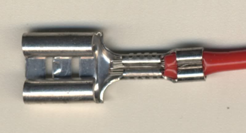
So to summarise - a properly made crimp is the best for automotive connectors designed to be crimped. But it needs the correct tool. I know the one I recommended is expensive, but it does a perfect job on most of the terminals you'd likely use when making your own loom. But not all. I have a dozen or so crimp tools for various applications. A decent crimp is shrunk round the conductor and gas tight. This can't be done with pliers.
Here's a pic of a crimp made with that tool:-
Last edited by DaveEFI on Wed Feb 05, 2014 11:05 am, edited 1 time in total.
Dave
London SW
Rover SD1 VDP EFI
MegaSquirt2 V3
EDIS8
Tech Edge 2Y
London SW
Rover SD1 VDP EFI
MegaSquirt2 V3
EDIS8
Tech Edge 2Y
Hi
It is worth remembering that Mil Spec is a time to something like 1% joint failure under "adverse" conditions, I don't remember all the details but adverse is similar to the environment under a bonnet of a tank!
For the military stuff, if you had to solder a wire into a terminal used to insist you used what was called a Jenkins Spring strain relief. First you slipped a piece of rubber sleeve onto your lead, stripped the wire for 1/4" and tinned it, took a piece of tinned copper wire 1 1/2 about inches long and soldered it to your freshly tinned wire so it was alongside the sleeving and ended at the tinned end. Soldered this to your terminal post, yes you are correct you did burn your fingers on tinned copper wire as you did this. Now that is all on the solder post you wing the tinned copper wire three times around the insulation, clip off the spare and slide the rubber sleeve over the whole lot. It was a total pain in the butt and took ages but it was a strain relief!
best regards
Mike
poppet valves rule!
