
Hi,
Think we have spoke before re this topic so watching with interest, i did get a spectre 9849 single air plenum of and aim to put a K&N cone filter via a 3" extension tube to get cool air at the front of the car.
Car is not with me at present so hoping to fit it when it returns
Martyn
Monkey business
Moderator: phpBB2 - Administrators

I saw this on a thread on retro Rides about Smokey Yunick's Chevelle and it made me think of this thread and recent conversations with a couple of Jag/Landrover development engineers about intake charge temps. Looks like Smokey took it seriously with a fully insulated filter housing and it looks like taking air from the high pressure area just in-front of the screen - Although with Smokey's reputation the bulkhead could be ducted away anywhere.

Get it from the lowest temperature area you can and keep it cool seems to be the advice.
Get it from the lowest temperature area you can and keep it cool seems to be the advice.
4.5L V8 Ginetta G27
Hi guys
I do have very limited space in my engine bay even though it looks quite big.
I have already utillised the pressure area at the base of the screen with my vent and this is where the air for the top filter is taken.
I have plenty of cold air coming in from behind the headlights hence the placement of the cone filters its now just a case of getting it into a decent With Smokeys set up there is plenty of space at the back of the bay and the secondary bulkhead and wish I could do something like that but behind my bulkhead there are a ton of hidden bits so its a no go area for sure.
Thanks for the advice and interest it is most welcome.
cheers
P
Evening all
After a lot of thinking and mind fabrication over the weekend I went back out to the workshop tonight with a reasonable idea of what was needed to make this work so out came some more of the foam and this is how the work panned out.
I cut and glued some blocks to the side of the housing allowing for enough room for the tubes to actually fit into the wedge shapes that will form the inlets.
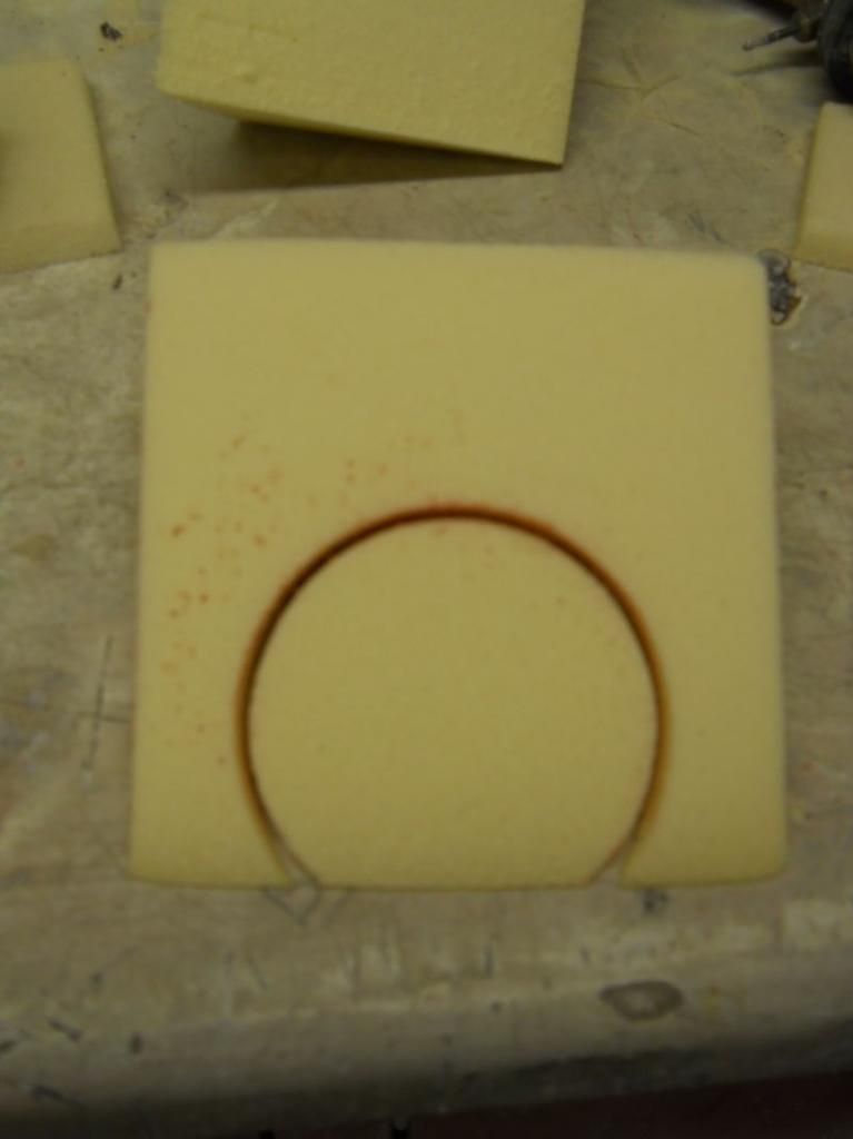
The difficult bit (for me anyway ) was to get exactly the right angle for the tubes to go into the wedges so what I did was cut a flat plate and then sat that on the tube making sure that it touched the face of the first block and ended up with this.
I know that this may be obvious to some of you but it made me scratch my head for a little while until I sussed it out.
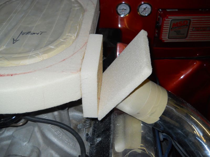
All I had to do then was to cut the wedge and dummy fit to see if it was right.
It was so then I scribed a line to square things off later.
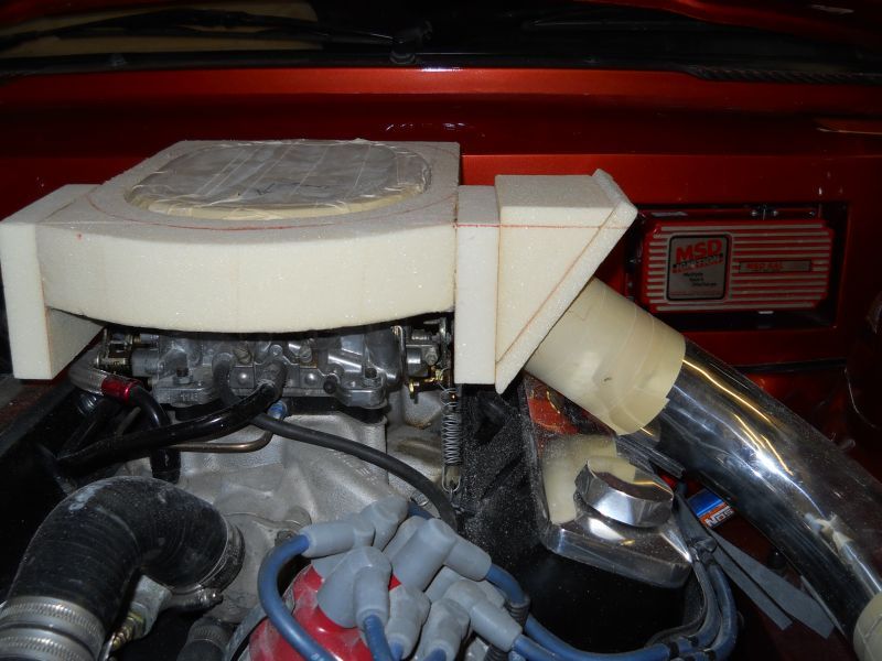
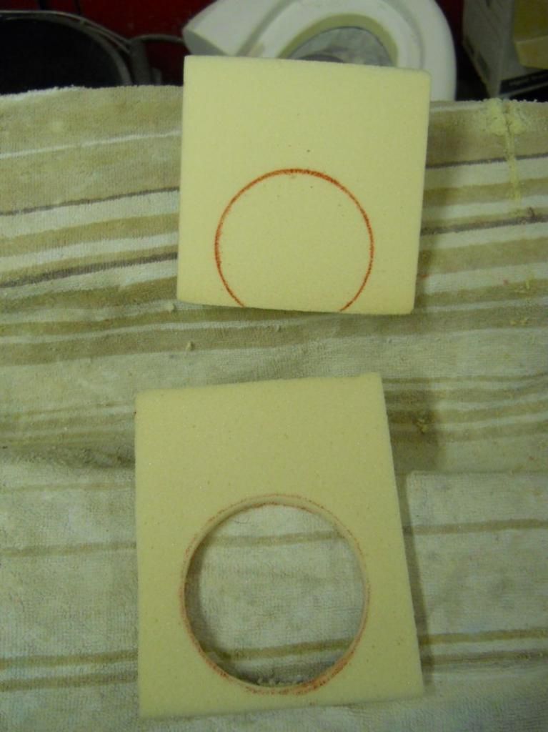
I transferred the outer tube dimensions onto the flat plate and then cut that out with a small section of gash tube.
That shape was then drawn onto the wedge and just cut into by about 1 1/2" to duplicate the angle for the little stub tube/connectors that will join the whole lot together at the end.
With that done all I had to do was to make an exact copy for the other side and glue the whole lot together using a couple of bricks to hold it all in shape.
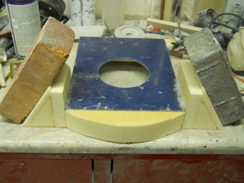
I can see no other way of joining the housing and the intake tubes together apart from using some silicon hose which will allow for engine movement and make housing removal possible with the minimum of fuss.
As for the front of the housing /filter assembly I plan to build that up into a plenum and then once it all fits together shape it nicely.
Now for a question to anyone out there reading my nonsense.
Can anyone carry out super neat TIG welding on this ali tube that I'm using as it's only 1.2 mm thick?
I have asked my local TIG guy and he says that his kit is far to powerful for such thin tube.
If you can help I would like to talk to you please.
That's it for tonight gents thanks for looking.
Cheers
P
After a lot of thinking and mind fabrication over the weekend I went back out to the workshop tonight with a reasonable idea of what was needed to make this work so out came some more of the foam and this is how the work panned out.
I cut and glued some blocks to the side of the housing allowing for enough room for the tubes to actually fit into the wedge shapes that will form the inlets.

The difficult bit (for me anyway ) was to get exactly the right angle for the tubes to go into the wedges so what I did was cut a flat plate and then sat that on the tube making sure that it touched the face of the first block and ended up with this.
I know that this may be obvious to some of you but it made me scratch my head for a little while until I sussed it out.

All I had to do then was to cut the wedge and dummy fit to see if it was right.
It was so then I scribed a line to square things off later.

I transferred the outer tube dimensions onto the flat plate and then cut that out with a small section of gash tube.
That shape was then drawn onto the wedge and just cut into by about 1 1/2" to duplicate the angle for the little stub tube/connectors that will join the whole lot together at the end.


With that done all I had to do was to make an exact copy for the other side and glue the whole lot together using a couple of bricks to hold it all in shape.

I can see no other way of joining the housing and the intake tubes together apart from using some silicon hose which will allow for engine movement and make housing removal possible with the minimum of fuss.
As for the front of the housing /filter assembly I plan to build that up into a plenum and then once it all fits together shape it nicely.
Now for a question to anyone out there reading my nonsense.
Can anyone carry out super neat TIG welding on this ali tube that I'm using as it's only 1.2 mm thick?
I have asked my local TIG guy and he says that his kit is far to powerful for such thin tube.
If you can help I would like to talk to you please.
That's it for tonight gents thanks for looking.
Cheers
P

Hello Gents
Well a very short session out in the workshop tonight as I seem to have injured my hand/wrist in some way during the day which is making things difficult and a bit uncomfortable to say the least but I have managed something.
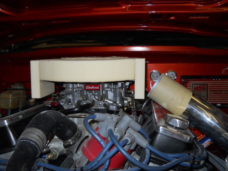
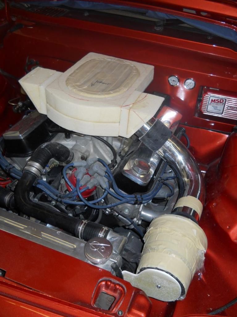
A set of four foam plates were glued together this morning in between jobs and this was just lightly glued into position tonight underneath to form the plenum.
Then I cut a section of tube and basically reamed that into the foam wings as shown last night.
Following that CHRIS (hee hee) I cut a 3" section of silicon tube and slid that onto the stub tube and then onto the main intake tube giving me the flexible joint CHRIS (again and no offence meant and hope none taken) that is needed on a set up like this.
At the moment the housing is way too ucking fugly and once all of the development work is done and please bear in mind I'm making this up as I go along I will start to fair it down to a much nicer shape and one that will be easier to make a mould from.
Yes the mould will be a grp unit so it can't be too complex a shape.
My hand was just about shot by this time so I had to stop but if it settles down overnight I will be back on task tomorrow.
Cheers
P
PS Mike I have been in contact with Tom and I think he can sort me out so thank you for your help with that

Well a very short session out in the workshop tonight as I seem to have injured my hand/wrist in some way during the day which is making things difficult and a bit uncomfortable to say the least but I have managed something.
A set of four foam plates were glued together this morning in between jobs and this was just lightly glued into position tonight underneath to form the plenum.
Then I cut a section of tube and basically reamed that into the foam wings as shown last night.
Following that CHRIS (hee hee) I cut a 3" section of silicon tube and slid that onto the stub tube and then onto the main intake tube giving me the flexible joint CHRIS (again and no offence meant and hope none taken) that is needed on a set up like this.
At the moment the housing is way too ucking fugly and once all of the development work is done and please bear in mind I'm making this up as I go along I will start to fair it down to a much nicer shape and one that will be easier to make a mould from.
Yes the mould will be a grp unit so it can't be too complex a shape.
My hand was just about shot by this time so I had to stop but if it settles down overnight I will be back on task tomorrow.


Cheers
P
PS Mike I have been in contact with Tom and I think he can sort me out so thank you for your help with that
-
Ian Anderson

- Forum Contributor

- Posts: 2457
- Joined: Sun Nov 19, 2006 9:46 pm
- Location: Edinburgh
Hey Paul it is looking great
Just an idea
Instead of hard mounting the air filters to the rad, how about mounting them from the front of the cylinder heads so they will move with the engine and you will not need the flex couplings etc.
Cheers
Ian
Just an idea
Instead of hard mounting the air filters to the rad, how about mounting them from the front of the cylinder heads so they will move with the engine and you will not need the flex couplings etc.
Cheers
Ian
Owner of an "On the Road" GT40 Replica by DAX powered by 3.9Hotwre Efi, worked over by DJ Motors. EFi Working but still does some kangaroo at low revs (Damn the speed limits) In to paint shop 18/03/08.
-
unstable load
- Top Dog

- Posts: 1285
- Joined: Mon May 04, 2009 6:53 am
I'm with Ian, but you could use silicon tube for the whole lot. That
will sort out any flexing.
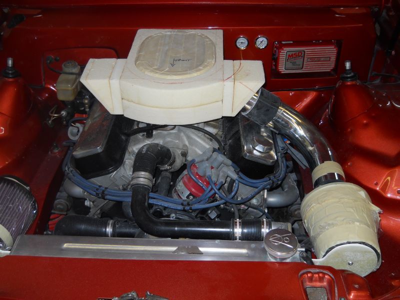
Not criticising here, Paul, but would it not be better for the sides of the "box" to be shaped to blend in the part where the pipes enter? In other words, the "ears" on the side could be blended in towards the rear giving more of a diamond shape, if not within the air box, just for the cover for a visual aesthetic?
will sort out any flexing.
Not criticising here, Paul, but would it not be better for the sides of the "box" to be shaped to blend in the part where the pipes enter? In other words, the "ears" on the side could be blended in towards the rear giving more of a diamond shape, if not within the air box, just for the cover for a visual aesthetic?
Cheers,
John
John
Looking at the lines from the brown felt tip on the foam on and around the RHS "Ear" that to me looks the way Paul is going.unstable load wrote:
Not criticising here, Paul, but would it not be better for the sides of the "box" to be shaped to blend in the part where the pipes enter? In other words, the "ears" on the side could be blended in towards the rear giving more of a diamond shape, if not within the air box, just for the cover for a visual aesthetic?
Best regards
Mike
poppet valves rule!
Hi lads
With regard to mounting the cones in front of the heads there just isn't enough room for them to go in.
My bonnet drops down to a vent over the rad which takes up the space.
Also because of this I only have about 10mm clearance on the top of the dizzy to under bonnet so try to get a 3" silicon tube in there would not work but I completely understand what you are saying and agree it would look better.
As for the shaping there is a lot to do with that and as already mentioned the current shape is only for setting the distances angles etc.
I plan to shave it down as much as possible because as it stands right now the bonnet will not shut so it will be considerably smaller and much more pleasing to the eye once final shaping has been done.
Thank you all for your comments though because they are most helpful and make me think from the other side of the fence.
Its very easy to get so fixated on what you think is right when in fact it is completely the opposite.
Cheers for now
P
