
I know someone on here put new cam bearings in a Rover V8 using an old camshaft, modified one way or another. I can't find the thread - does anyone know where it is?
And does anyone have photos of this sort of thing? I want to replace the bearings but a machine shop is a long way away from here.
DIY Cam Bearings with an Old Camshaft
Moderator: phpBB2 - Administrators
I could see how that is feasable - probably involves making a sleeve or collar that turns the old bearing surface into a mandrel.
Dont forget that you need to align the holes in the bearing with the oil gallery holes.
Bit of googling founds Chris's site with the dimensions - surely you could send the details to a tame machine shop and get them posted out to you?
http://www.cowdery.org.uk/downloads/V8-Cam-brg-tool.pdf
Dont forget that you need to align the holes in the bearing with the oil gallery holes.
Bit of googling founds Chris's site with the dimensions - surely you could send the details to a tame machine shop and get them posted out to you?
http://www.cowdery.org.uk/downloads/V8-Cam-brg-tool.pdf
-
Davo
- Helpful or Confused

- Posts: 72
- Joined: Tue Feb 12, 2008 5:51 am
- Location: Derby, The Kimberley, Western Australia
You know, I've been all over his site but I missed that somehow! Thanks for that, I do have a machine shop with grown-ups in it that will do a flywheel by post, so I might try them for this.
Last edited by Davo on Thu Mar 21, 2013 1:35 pm, edited 1 time in total.


-
Davo
- Helpful or Confused
- Posts: 72
- Joined: Tue Feb 12, 2008 5:51 am
- Location: Derby, The Kimberley, Western Australia
Well, I finally made the tool and wrote a long post about it, which then disappeared as the forum timed out.
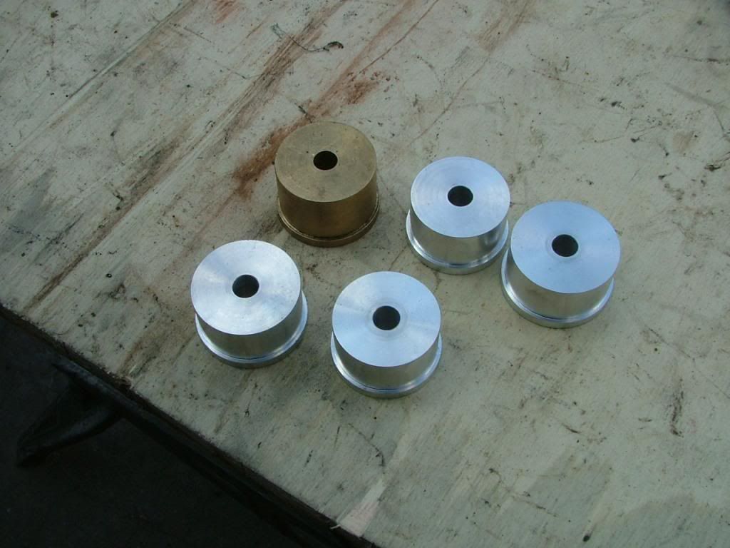
So what I did was to use some ½” UNF threaded rod and I made the various-sized bits to suit. I chopped up an old camshaft and wound up with five bearing journals, but with just an angle grinder it was about impossible to get nice flat faces where they’d been cut. Then I drilled ½” holes through them all, but even with a drill press it’s also about impossible to get them exactly through the centre, so they all wound up a bit wonky. These camshaft parts being hardened steel, I used various cobalt bits in stages with lots of cutting oil spray, and that went well, and though the ½” bit was only HSS it survived too.
These parts go into their respective bearings, but you also need washers that are just shy of the bearing OD, because these are what push against the shoulder of the bearing to get the old ones out and the new ones in. I did have some big thick washers but they all needed to be carefully trimmed, and once again with only an angle grinder it’s pretty dodgy to get them just right, though possible.
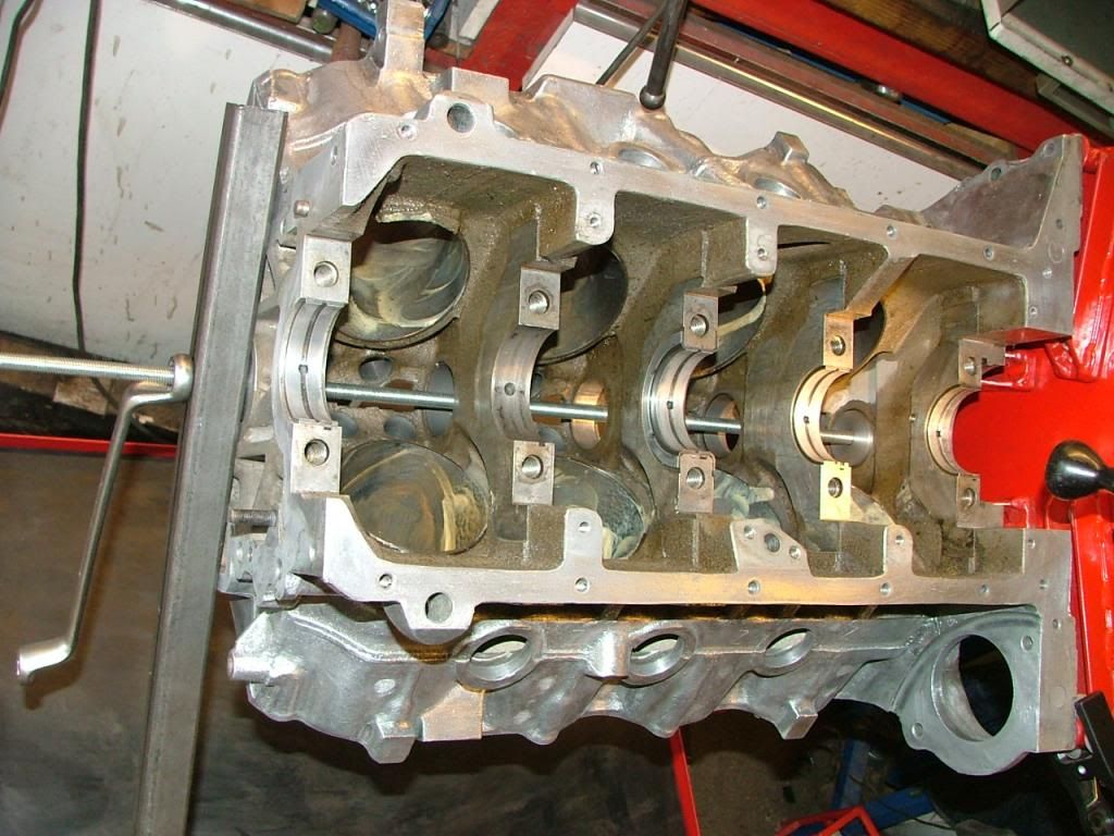
After the usual swearing, I had each washer made up. Luckily I had an old block to practise on and I figured out what to do. I assembled one of the journals I wasn’t using as a backing for the washer, then the washer itself and then the journal for whatever bearing I was working on. A nut on either side of the whole mess kept it together, which was important since it all had to be adjusted to line up properly. In some instances it had to be assembled inside the block.
Knocking out the old bearings wasn’t too bad but you do have to be very careful not to damage the block. Check and check again if you run into trouble. I found it’s best to remove the old bearings from the back, hitting towards the front, and from front to back to put the new ones in. Start at the rear bearing and work your way to the front.
The proper tool, apart from being square, should also have a cone at one end to help keep the rod square in the bearing tunnel. This is where I knew I needed a lathe, because the crooked DIY thing I’d made had no way to do this.
Each new bearing has a bevel on one end to help get the thing in, and you also have to remember to mark the bearing and block so that the oil holes line up. I used a little oil to help and then had to check and check to make sure the bearing was square, which it usually wasn’t, but at least they did square up as they went in. None of them took much force with the mallet, which is always a good sign.
The front bearing must be recessed a bit to sit in the right spot for the cam journal – just measure how much on the cam for reference.
A test fit with a camshaft showed not a bit of tightness or trouble fitting it so the bearings must have survived the process. Though I did put a slight scratch on one with the cam, I don’t think it will matter too much since the block was upside-down so the scratch is at the top, or the unloaded part of the bearing.
It all worked, but I’m in the middle of nowhere and I wasn’t about to send this block away for two or more weeks to get this done, but if you have a good shop nearby – or a lathe – I’d recommend that instead.
So what I did was to use some ½” UNF threaded rod and I made the various-sized bits to suit. I chopped up an old camshaft and wound up with five bearing journals, but with just an angle grinder it was about impossible to get nice flat faces where they’d been cut. Then I drilled ½” holes through them all, but even with a drill press it’s also about impossible to get them exactly through the centre, so they all wound up a bit wonky. These camshaft parts being hardened steel, I used various cobalt bits in stages with lots of cutting oil spray, and that went well, and though the ½” bit was only HSS it survived too.
These parts go into their respective bearings, but you also need washers that are just shy of the bearing OD, because these are what push against the shoulder of the bearing to get the old ones out and the new ones in. I did have some big thick washers but they all needed to be carefully trimmed, and once again with only an angle grinder it’s pretty dodgy to get them just right, though possible.
After the usual swearing, I had each washer made up. Luckily I had an old block to practise on and I figured out what to do. I assembled one of the journals I wasn’t using as a backing for the washer, then the washer itself and then the journal for whatever bearing I was working on. A nut on either side of the whole mess kept it together, which was important since it all had to be adjusted to line up properly. In some instances it had to be assembled inside the block.
Knocking out the old bearings wasn’t too bad but you do have to be very careful not to damage the block. Check and check again if you run into trouble. I found it’s best to remove the old bearings from the back, hitting towards the front, and from front to back to put the new ones in. Start at the rear bearing and work your way to the front.
The proper tool, apart from being square, should also have a cone at one end to help keep the rod square in the bearing tunnel. This is where I knew I needed a lathe, because the crooked DIY thing I’d made had no way to do this.
Each new bearing has a bevel on one end to help get the thing in, and you also have to remember to mark the bearing and block so that the oil holes line up. I used a little oil to help and then had to check and check to make sure the bearing was square, which it usually wasn’t, but at least they did square up as they went in. None of them took much force with the mallet, which is always a good sign.
The front bearing must be recessed a bit to sit in the right spot for the cam journal – just measure how much on the cam for reference.
A test fit with a camshaft showed not a bit of tightness or trouble fitting it so the bearings must have survived the process. Though I did put a slight scratch on one with the cam, I don’t think it will matter too much since the block was upside-down so the scratch is at the top, or the unloaded part of the bearing.
It all worked, but I’m in the middle of nowhere and I wasn’t about to send this block away for two or more weeks to get this done, but if you have a good shop nearby – or a lathe – I’d recommend that instead.

-
stevieturbo
- Forum Contributor

- Posts: 4081
- Joined: Sat Nov 18, 2006 6:22 pm
- Location: Northern Ireland
Ideally you should have used a tapered cone at the "pull" end to ensure the rod stays 100% central at all times.
And a larger 20mm or 3/4 threaded bar will make for a stronger and easier pull for installing the bearings.
Videos online show people hammering bearings into place with a similar rod/toll, although I'd prefer the threaded rod and pulling them in smoothly.
And a larger 20mm or 3/4 threaded bar will make for a stronger and easier pull for installing the bearings.
Videos online show people hammering bearings into place with a similar rod/toll, although I'd prefer the threaded rod and pulling them in smoothly.
9.85 @ 144.75mph
202mph standing mile
http://www.youtube.com/watch?v=XgWRCDtiTQ0
202mph standing mile
http://www.youtube.com/watch?v=XgWRCDtiTQ0
-
Davo
- Helpful or Confused
- Posts: 72
- Joined: Tue Feb 12, 2008 5:51 am
- Location: Derby, The Kimberley, Western Australia
Photos! Thanks! That's the other thing I was going to say: that the plan in the link above would be good to take to a machine shop, just as long as you could find a capable one that would do a little job like that. I'd add the centring cone to the plans as well. I'll still do them myself in the future because I've had a heap of trouble with various "professionals" over the years.
