
Mrs Gelmonkey is going to help me sort out a link to the Autometer website later so that you can see for yourselves the wiring diagram.
As I am only used to chucking fibreglass about i am seriously lacking in computer skills.
I have sent an e mail to Autometer to see if they can shed any light on this for me aswell.
Thanks again for your help with this.
Hopefully it will be sorted soon
cheers
P
electric speedo drive testing
Moderator: phpBB2 - Administrators
The doc Ramon sent me shows the sensor to be active - it has a couple of transistors inside it. So it would need the 12v supply to work, which is why a DVM doesn't show an output.
I'd try wiring the sensor to the 12 volt supply as Rover does it, but with a 1k ohm resistor to ground on the other leg, and take the output to the speedo off the 'top' of that resistor. If that doesn't make sense I'll post a proper circuit.
I'd try wiring the sensor to the 12 volt supply as Rover does it, but with a 1k ohm resistor to ground on the other leg, and take the output to the speedo off the 'top' of that resistor. If that doesn't make sense I'll post a proper circuit.
Dave
London SW
Rover SD1 VDP EFI
MegaSquirt2 V3
EDIS8
Tech Edge 2Y
London SW
Rover SD1 VDP EFI
MegaSquirt2 V3
EDIS8
Tech Edge 2Y
Hi Again
I have had a reply from Autometer and this is what they are saying...
Paul,
A couple important things. First of all, if it’s a 3 wire sensor, it requires 12 volts to the sender. If it’s a 2 wire, it does not use 12 volts. Second, the speedometer does not have to be calibrated to work. Upon proper installation, the speedometer should work; it will likely just be inaccurate until it’s calibrated. Therefore, focus on just getting the speedometer to operate before calibrating it.
From our experience the number one issue with speedometer not operating is an insufficient ground. The speedometer can power up with a sufficient 12 volt ground reference, but there also be a ground reference for the signal. This can be accomplished by making sure the sender is grounded to the engine and the speedometer is grounded to the engine. This is an engine ground, not chassis, or battery negative ground. It’s important that it is the engine.
Yes, as a last resort you are welcome to send the sender and speedometer back to us.
Thank you,
Matt
So will try this tonight but will also post up the info as mentioned in a previous post today.
cheers
P
Hi Guys
Here is the wiring diagram and all the relevant info.....
http://www.autometer.com/productPDF/1140.pdf
Thanks and see what you think
cheers
P
Here is the wiring diagram and all the relevant info.....
http://www.autometer.com/productPDF/1140.pdf
Thanks and see what you think
cheers
P
Hi Again all
Well I have tried Autometers suggestion of running the earths from the sender and the guage to the block and fired the sucker up and guess what..
F**k all changed apart from the fact that when I turned the ignition on beforehand I used to see 16000 in the digital display now after trying the AM way I now get 550 showing in the display which says to me that now there really is a problem!
Never seen that figure before and AM say that you should always see 16000 when you turn the ignition on.
Have phoned Autometer now and am waiting for a call back,why not,use their phone bill instead of mine.
Will keep you posted .
ARRGGHHHH
P
Dave
Do you think that you could post a wiring diagram for me please.
I never got a call back from Autometer last night and to be honest I was really p@ssed that their advice did not make the slightest bit of difference.
As already mentioned I am not brilliant at wiring but think I should give it a go becasuse I dont want to send the speedo back to the USA unless I really have to.
To say I'm frustrated would be an understatement.
Cheers
P
-
russell_ram

- Getting There

- Posts: 238
- Joined: Mon Nov 20, 2006 1:03 pm
- Location: Midlands
I agree with Dave here - the Rover sender is a two wire Hall effect. You need 12V supply and ground reference. I use on (admittedly with a smiths guage) and it works perfectly when wired correctly. The speedo is only counting pulses, so the fact you are using autometer shouldn't make any difference at all.
Russ
Russ
Rover Powered to 11.63sec @ 128mph.
This is what I'd try - adding a resistor.
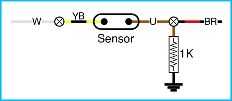
It can't do any harm, and should add the ground to power the sensor electronics which is how I think the Rover speedo does it. But it really is a guess as I don't have a spare sensor to check out.
It can't do any harm, and should add the ground to power the sensor electronics which is how I think the Rover speedo does it. But it really is a guess as I don't have a spare sensor to check out.
Dave
London SW
Rover SD1 VDP EFI
MegaSquirt2 V3
EDIS8
Tech Edge 2Y
London SW
Rover SD1 VDP EFI
MegaSquirt2 V3
EDIS8
Tech Edge 2Y
Hi Dave
Thank you for the diagram.
Can I buy this kind of resistor at Maplins and should I just ask for a 1k resistor?
I will not be able to do anything with this now until early next week as I have to go and work in Trowbidge for the next couple of days on a Willy's Coupe and then Mrs G is away for the weekend so will be looking after the small people.
Thank you so much for all of your help and I will get this sorted just in time for the car to come off the road for the winter!!
Cheers
P
-
Ian Anderson

- Forum Contributor

- Posts: 2453
- Joined: Sun Nov 19, 2006 9:46 pm
- Location: Edinburgh
Little people are good for electronic workgelmonkey wrote:Hi Dave
then Mrs G is away for the weekend so will be looking after the small people.
Cheers
P
ask them to hold the nd of the wire and when it comes live they always let you know!
Like the time I was on a farm and said to my daughter that shock wire on the top of the fence is not working - she then had to touch it to check!
Ian
Owner of an "On the Road" GT40 Replica by DAX powered by 3.9Hotwre Efi, worked over by DJ Motors. EFi Working but still does some kangaroo at low revs (Damn the speed limits) In to paint shop 18/03/08.
Mr Anderson
you have a cruel sense of humour which I like.
However,my daughter does not like the pin up pictures I have in my garage and No2 son likes them too much so not the best place to have them help me.
As an aside some years ago George was "helping" me put the engine together for my car and I told him we were going to put the slugs in next.
He said "I'll go and get some for you dad"
"I have them here son " I said and then he vanished out to the garden in search of .....
Whilst they do have an enourmous amount of squish thems not quite the right ones.
Was only trying to help he was....
Kids!!
P
