
Guys, does anyone know where the most restrictive part of the heads are... is it the usual place around the valve gides, how far can I take it, or are the heads on the 3.5 OK as standard? Think the heads I've got are from the twin plenum modle as the tappet adjusters are welded (aparently only the twin plenum had this done?)
Cheers
Jono
Rover 3.5 head porting??
Moderator: phpBB2 - Administrators
-
CastleMGBV8
- Top Dog

- Posts: 2334
- Joined: Sat Aug 18, 2007 5:09 pm
- Location: Sidcup, Kent, UK
Jono,
No standard RV8 had adjustable rockers and if yours are welded then they are from a group A race engine! in which case it's worth having a close look at the engine to see what you might have.
Have you stripped it down and if so does it have solid lifters or hydraulic? Any sign of head work and if possible what is the cam if marked? if it's a WL3 then there could be a lot more special parts.
Essential to keep the lifters matched to the lobes of cam if parts are reusable
What are intending to use the engine for Road/track day/race?
Let us know what you have, and intended usage and further advice can be offered.
Kevin.
Hi
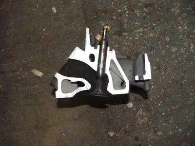
the most restrictive part of the rover head is where the port narrows for the pushrods to pass through the heads, reffered to as the "Push rod pinch" on the rover it is particulally bad as it forces the port to "kink" and tends to cause the flow to become turbulant. Just opening the outer ends of the ports to the gasket face just tends to make this tendency to turbulant flow worse you need to get this bit sorted first.
Best regards
Mike
poppet valves rule!

-
goodsy1968
- Newbie

- Posts: 38
- Joined: Sat Nov 18, 2006 9:37 am
- Location: Spalding
"Best place to modify is just behind the valve seat, by smoothing out the factory cuts will yield good results."
very true, a basic blend and clean up of the area does alot for these heads, also opening the seat inserts by a couple of MM then giving them a three angle job and a back cut on the inlet valve.
The most restrictive part, as the question asked, is still the pushrod area.
On pre cross flow ford engines which had this problem of a very crowded port area they used to build a whole new inlet trace area by welding in a tube from above, creating a semi down draught head, I have seen photos of some '60s chevy (I think) heads where the inlet port comes in from the "wrong"side of the head and rocker gear for a fully down draught head. I am suprised no one has had a go at this aproach with the rover.
Best regards
Mike
poppet valves rule!

Re: Rover 3.5 head porting??
Not sure I know what you mean by that?Jono FD3 wrote:Think the heads I've got are from the twin plenum modle as the tappet adjusters are welded (aparently only the twin plenum had this done?)
Chris.
--
Series IIA 4.6 V8
R/R P38 4.6 V8
R/R L405 4.4 SDV8
Series IIA 4.6 V8
R/R P38 4.6 V8
R/R L405 4.4 SDV8
Hi
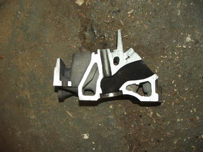
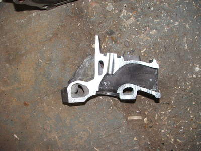
Those sections are perfect for expaining what I mean, looking at the first of the 2 pictures of the inlet port, the idea would be to drill a big hole into the roof of the port at about 30 degrees from the valve centre line pointed at the valve head dead centre with the the side of the hole toward the valve terminating just shy of the valve guide. Then push a piece of ally tube into the hole so that when it is trimmed correctly it seals off the old port where it turns over to meet the side of the head and weld it in, net result a nice straight inlet port pointing straight down at the back of the valve. Not even any water passages in the way! In reality for it to work well the ally tube would need to have about 4mm wall thinckess minimum and it would need to be tapered at about 4-5 degrees but is would give much better flow. Yes the rocker covers will need modifying and probably have to cut some holes in MGB bonnets to make room for the throttle body stacks.
If you have a look at this link, http://www.historicracing.org.uk/parts/engine.html
there are some examples of how the ford heads were modified, scroll down and look at the ford "MAE DD" heads (down draught) there a few examples, the best one is the 1000 cc screamer f3 heads with the ends of the tubes above the head upper surface and where the ports originally exited.
Another example here http://www.yarwoodeng.co.uk/latest-spec ... d-80-p.asp
Best regards
Mike
poppet valves rule!
