I'm removing an Opus dizzy with the silver block behind the coil & replacing it with a dizzy I bought off e-bay which I think is a DLM? - AMP on side of casing.
So far:
The 'amp on side' has 3 pins out - got an adaptor so I now have 2 pins out. I'm told one is coil neg & the other is coil pos. Do these plug straight onto the coil? - & will the Opus coil suffice?
Also, there is another terminal next to the amp on the dizzy. Whats this for?
Where does the 12v feed come from to power the coil - is it a case of finding this feed & plugging it onto the coil pos? (on the Opus I presume it comes from somewhere in the silver block thingy).
Related to the above, will I find a feed on the 'starter' side of the silver block behind the coil? If so, what happens to wiring into & out of the silver block thingy once I fully convert to the DLM?
This may seem I'm rambling, but I've spent the last week fitting the engine & I'm running out of time/patience to get it going.
(In desperation I put the old Opus setup back on last night & the engine fires but wont run, even though it ran before).
Some pics for reference:
New Dizzy with 2-pin adaptor fitted

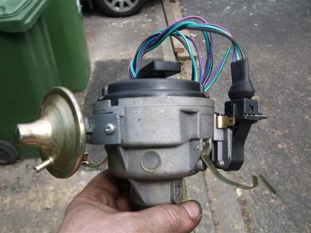
new dizzy as supplied 3-pin wiring. also shows another terminal next to the amp - whats this for?
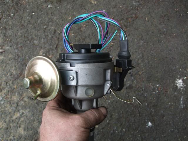
another view
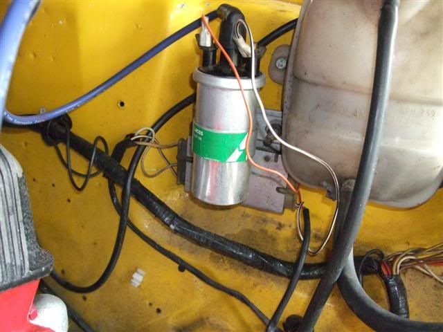
existing Opus silver block. left side is stamped 'starter in' with white & white/black wires & right side is plug shown on next picture