
[quote="katanaman"]Your obviously something to do with this site/company so I wouldnt be too surprised if you get a few skeptical posts. You like to compare patcrank system to other manufacturers, are there any real working engines out there with this system or is it all 3D modelling and animation?[/quote]
I have more than something to do with this site/company. Is it bad?
I better like the sceptical posts than the others.
And I like to compare the pattakon projects to those of big manufacturers.
Every project starts by paper, calculations, animations patenting and so on.
In the pattakon web site you can see several such projects, for instance the pattakon VVA Civic prototype running at 9.000 rpm / 12mm valve lift and idling at 330 rpm, without any throttle. Unless I am wrong, there is no other such VVA in the market, from any manufacturer.
It was initially on paper, then on animations and finally in the car and the car on the road for tests. See in the datalogs the aspiration of the engine at 9000rpm.
The pattakon OPRE diesel engines also started from paper and animations. Now the prototype engines are working as theory predicts.
In comparison the VCR projects are way simpler.
An engineer has to be able to predict the problems and the advantages.
Believe it or not, everything works as the (correct) theory predicts.
The pat-head VCR is the correction of SAAB's SVC. It is very similar and yet very different than SAAB's SVC. So, to what to compare it?
And the patcrank VCR is the correction of Nissan's, Daimler's, Honda's multilink VCRs. Isn't reasonable to compare patcrank with their design?
Photos and videos from the VCR prototypes will be published at the proper time.
What I expect from your technically oriented members is to write their objections.
Thanks
Manousos
Variable Compression Ratio V-8
Moderator: phpBB2 - Administrators

The big problem with GDi is that you cant use a cat as cats only work with stoichiometric mixtures, not stratified or lean burn mixtures. however NOx storage catalysts using barium are being developed to solve this. if this is solved, their fuel efficiency (especially with the nex generation of injectors being developed) is very close to that of dieselskatanaman wrote:GDI has been around for a good few years now but has never really taken off. It was probably about 10 years ago that Mitsubishi started selling it on their main stream cars. Its a benefit but it doesnt seem to have been a major benefit. Wotlands post seems like a solution that atleast is working although it does seem very complicated and at a guess wear prone.
I think the real question is, how long are manufacturers going to continue to develop the IC engine? It makes sense in the short term but not in the long term.
as for the IC engine.... it will be around for at least the next 50 years, whether in bio-fuel, petrol or diesel form
fuel cells are still a no go as the CO2 emmisons are massive to create the fuel cells, so it doesnt pay off until after MANY thousand of miles (close to 100k usually) and there is a similar prob with the batteries for hybrids
also just to fit the hydrogen infrastructure in britain alone would cost over 10 billion quid. no one will build lots of H2 pumps if there arent many cars, and manufacturers wont build cars unless there is a network of pumps to fill them. catch 22 really! hence it is a slow process, rather than an overnight thing
H2 powered IC cars might become more popular when they solve the H2 storage issue... metal oxide is the current leader but it is expensive and still has problems
phew.... i need a sit down now!
Zander
Take a look at Gomecsys web site.Rossco wrote:Looking at this it appears to me that the big ends would have to be prohibitively large in order to accommodate the additional secondary crank mechanism.
Also you end up with 2 sets of bearings per journal, one of which is constantly rocking across the same path. Wear is going to be a real issue with that bearing set.
Also not sure how you would assemble this onto a crank unless each of the secondary crank journals were also split.
Again another area of potential wear and failure.
Their prototypes use the eccentric ring architecture (between crankpin and big end bearing of conrod).
The problem in Gomecsys engine is the need for gear wheels to control the motion of the eccentric ring, that degrades the strength of the crankshaft and the support of the crankshaft on the crankcase.
Read the analysis at www.pattakon.com/patcrankVCR.htm for the bearings velocity. Things are much better for patcrank than for the Gomecsys and the multilink VCR of Nissan.
For the assembly, take a look at the patcrank6.exe animation.
Thanks
Manousos

No its not bad to be connected, I just wanted to point out that people will always think of smoke and mirrors so may seem negative in some cases. Its also not bad to compare your designs against major manufacturers except in the case of VCR you dont have any proof that the concept works or none that your willing to share at any road  . Sorry but just about every product out there has published why their product is better than everyone else's and they cant all be the best. As they say the proof of the pudding is in the eating so I look forward to seeing videos of your concepts running in the future.


I like the idea of the crankless GRECO engine. I think it would need helical gears though.
I'm not sure how you'd share the power between the two crankshafts, and how you'd manage backlash as any backlash would upset the alignment of the piston assembly.
Chris.
I'm not sure how you'd share the power between the two crankshafts, and how you'd manage backlash as any backlash would upset the alignment of the piston assembly.
Chris.
--
Series IIA 4.6 V8
R/R P38 4.6 V8
R/R L405 4.4 SDV8
Series IIA 4.6 V8
R/R P38 4.6 V8
R/R L405 4.4 SDV8
Think of a three-inline Greco, as in the http://www.pattakon.com/greco/Grecoi3.exe animation, having two counter-rotating electric generators, one at each side of the engine, each electric generator driven by "its own" crankshaft. This way the sybchronized gearwheels stay unloaded and the backlash is minimized.ChrisJC wrote:I like the idea of the crankless GRECO engine. I think it would need helical gears though.
I'm not sure how you'd share the power between the two crankshafts, and how you'd manage backlash as any backlash would upset the alignment of the piston assembly.
Chris.
The basis of the power plant is rid of inertia vibrations of any order (like a V-12 or a Wankel Rotary engine power plant) but it is also rid of power pulses vibrations of any order too (which is not possible for the V-12 and the Wankel power plant).
The question is the reliability, because the rollers transfer by line-contact the complete piston loads (gas pressure and inertia) to the cams.
By the way, you can take a look at the "conventional" OPRE.
Thanks
Manousos
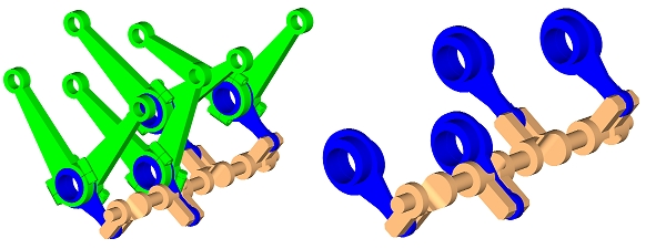
The basics of V8 patcrank VCR are shown in this simple gif animation:
The main crankshaft (red) is conventionally supported on the crankcase and drives conventionally the flywheel and the gearbox.
If you do not want to open the "exe" animation for more, you can alternatively open the:
http://www.pattakon.com/patcrank/patcrankVCR.wmv
WMV video animation.
Manousos
The main crankshaft (red) is conventionally supported on the crankcase and drives conventionally the flywheel and the gearbox.
If you do not want to open the "exe" animation for more, you can alternatively open the:
http://www.pattakon.com/patcrank/patcrankVCR.wmv
WMV video animation.
Manousos
