Need help with electrical unkowns!?

General Chat About Electrics, And Ignition Systems.

Moderator: phpBB2 - Administrators

Post Reply
Seedy Al
Newbie
Newbie
Posts: 3
Joined: Thu Jan 29, 2009 8:56 pm
Location: New Zealand
Contact:

Need help with electrical unkowns!?

Post by Seedy Al »

hey guys
have been browsing the forum for a few answers reguarding a job I have been working on for a customer.

Basicly im trying to wire up a injection rover v8 into a TR6, and i have gotton a bit stumped.
things i am having problems with are the coil wiring and the crank angle sensor etc

So here Goes

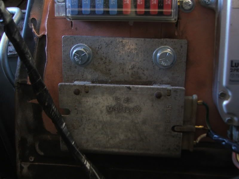
there is a metal block, on one side it has Distributor stamped into it with a plug coming out of it, from order from top to bottom the wires out of the plug read
Green
White/brown
White

on the other side of the block it has "Start SW +"
i have no plug for this so have no idea what colours or feeds are meant to be going in or out of it.

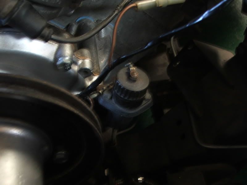
the wires from the crank angle sensor are
green
black/red
and also a brown there with a bullet connector

And also From the distributor there is a white with black tracer and a red with black tracer.

Also, i dont know what wires went to the coil. i have one wire that has been labeled for the neg side of the coil and is White with a black tracer which i would imagine would match the one to the distributor

and while im at it i also have a relay which is all wired into the injection loom besides one wire which is a white with blue tracer.

im not sure what the injection is out of, but it is Flapper type.

if anyone can help me that would be great!
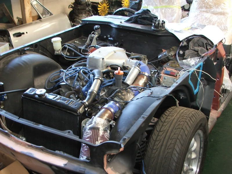
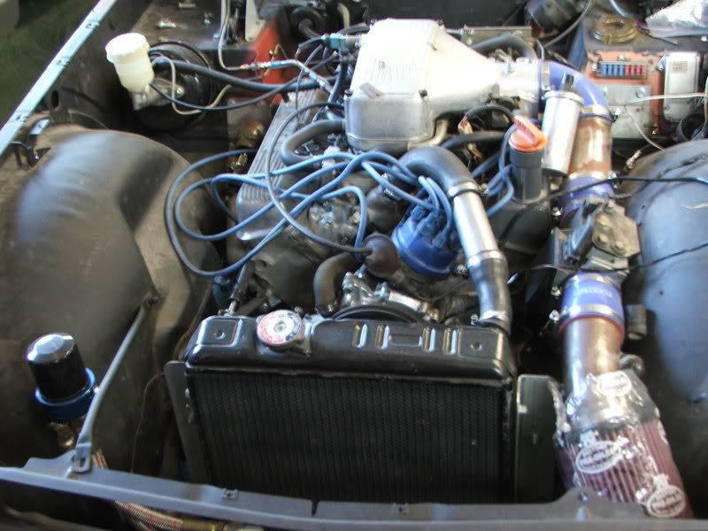
i work for a company Called Classic Car Services in New Zealand, heres some pics of the TR6 pig and the wiring

The box
Image

Crank angle and diagnostics
Image

And the Engine bay
Image

Image

Also have wired up the computor as written on this forum, so this is pretty much the last stuff before i can test it
thanks in Advance for any hlep, Cheers guys

Allan


User avatar
Pocket rocket
Getting There
Getting There
Posts: 256
Joined: Sun Nov 19, 2006 1:08 am
Location: Hawkinge, Kent

Post by Pocket rocket »

The aluminium box is the ballast resistor unit that is part of the OPUS system (Lucas 35DE8 distributor).

This is the wiring for that system Image[/img]
User avatar
ChrisJC
Top Dog
Top Dog
Posts: 5077
Joined: Mon Nov 20, 2006 1:13 pm
Location: Northants / Cambs
Contact:

Post by ChrisJC »

A few comments:
- Ignore the crank angle sensor - it's only for diagnostics, and isn't needed to run the engine.

- As for the ignition, I would ditch that setup and fit a later ignition-amp-on-distributor-body with matching coil. That way there's no ballast resistor or any of that complicated stuff. Just +12V-ignition supply to coil and amplifier and a wire between amp & coil -ve. That is also the ignition system that was designed for use with the EFi system you have.

- The white/blue wire from the relay is the coil -ve feed into the ECU to tell it that the engine is turning. It should be connected to coil -ve.

- That rad looks quite small. Might be a bit marginal.

For the wiring diagram, the best place is the Land Rover manual for the Range Rover classic 3.5 EFi, chapter 19. That gives you the engine loom, and the Haynes Range Rover classis manual gives you the rest of the vehicle. The two connected at a 4 (or 5) pin connector, with +12 permanent, +12-ign, cranking signal and fuel pump feed.

Chris.
--
Series IIA 4.6 V8
R/R P38 4.6 V8
R/R L405 4.4 SDV8
Seedy Al
Newbie
Newbie
Posts: 3
Joined: Thu Jan 29, 2009 8:56 pm
Location: New Zealand
Contact:

Post by Seedy Al »

Thanks heaps guys, that was super helpful, might be bale to get the thing running now

:)

Cheers.
Allan
User avatar
Darkspeed
Guru
Guru
Posts: 913
Joined: Sun Sep 02, 2007 4:43 pm
Location: Shropshire
Contact:

Post by Darkspeed »

This is useful as well as it lets you know whats going on on the inside of that little alloy box.

Image
4.5L V8 Ginetta G27
Seedy Al
Newbie
Newbie
Posts: 3
Joined: Thu Jan 29, 2009 8:56 pm
Location: New Zealand
Contact:

Post by Seedy Al »

hey guys thanks for all your help with that
So we have finally got round to trying to start the thing, have wired up the bits and pieces you have shown

but, seem the injectors dont want to fire, which got me thinking, Should there be any other feeds from the crank angle/ dissy/ coil side of things to the ECU side besides the blue/white wire off the coil - ?

Cheers in advance,
Allan
User avatar
ChrisJC
Top Dog
Top Dog
Posts: 5077
Joined: Mon Nov 20, 2006 1:13 pm
Location: Northants / Cambs
Contact:

Post by ChrisJC »

The ECU only needs coil -ve, +12V, +12V ign and cranking signal.

You can check the ECU is alive by quickly opening the throttle. You should hear all the injectors pulse when you do that (it's the enrichment system)

Also you can open the flap in the AFM then the fuel pump should start. (the cranking signal also starts the fuel pump)

Otherwise you're into checking the sensors at the ECU multiplug.

Chris.
--
Series IIA 4.6 V8
R/R P38 4.6 V8
R/R L405 4.4 SDV8
User avatar
Ian Anderson
Forum Contributor
Forum Contributor
Posts: 2448
Joined: Sun Nov 19, 2006 9:46 pm
Location: Edinburgh

Post by Ian Anderson »

Hi Al

don't forget to make sure your oil is primed before you fire it up

Ian
Owner of an "On the Road" GT40 Replica by DAX powered by 3.9Hotwre Efi, worked over by DJ Motors. EFi Working but still does some kangaroo at low revs (Damn the speed limits) In to paint shop 18/03/08.
Post Reply

Return to “Electrical & Ignition Area”