
Im going to have a crack at setting the timing tomorrow. If I warm the engine up and disconnect the vacuum advance what do I set the timming too? I have a snazzy snap on timming gun to play with so should be able to get it right.
Cheers
Setting timing with strobe
Moderator: phpBB2 - Administrators
-
ramon alban
- Knows His Stuff

- Posts: 667
- Joined: Fri Nov 17, 2006 11:22 pm
- Location: Bedford UK
- Contact:
Re: Setting timing with strobe
Hello Stan,satancom wrote:------- If I warm the engine up and disconnect the vacuum advance what do I set the timing too? -------
Thats a pretty open question without knowing the engine age, type, C.R. and other details but the simple answer is "about 4 Deg BTDC", but you may wish to read the following extract from my upcoming Rover SD1 V8 Efi ignition essay (work in progress) which explains what is a very straightforward process for normal motoring.
Ignition Timing
Not a normal maintenance issue because it does not randomly vary unless there is mechanical malfunction or uninformed dabbling. Changing fuel grades or vendors occasionally will make small efficiency differences so it is best to stay with the same fuel if possible but changing grade/vendor permanently may necessitate a timing change to optimise burn efficiency.
Before making a change check the timing marks on the front pulley/damper are legible. If not, clean with solvent and fill the indentations with white wax crayon or Tippex. Rub off the excess.
When Rover built these V8 engines the amount of ignition advance at idle was about 6-8 degrees before top dead centre (BTDC). Nowadays we have little or no access to high octane, leaded fuel so the ignition timing has to be adjusted for best burn efficiency. Typically the timing should be retarded by 4-6 degrees, so one might expect the timing at idle to be set around 2-4 degrees.
Timing procedure may vary according to the equipment being used but in the case of a simple stroboscopic timing lamp ensure the setting is made below normal idle speed (say 600 rpm) and with the vacuum advance tube disconnected from the plenum pipe. Loosen the clamping bolt just enough to allow the distributor to rotate. Follow the manufacturer’s instructions and set the timing to the appropriate figure. Reconnect the vacuum advance tube and readjust the idle speed to the normal setting. Secure the distributor clamping bolt unless moving on to the next step.
With the distributor clamp bolt loosened sufficiently for the unit to be rotated without undue force, take the car out for its final ignition timing adjustment selecting a route where one can subject the engine to heavy uphill acceleration at low engine speed in a higher gear to listen for pinking, the high-pitched knocking noise, caused by premature detonation. If pinking is present, stop the car and rotate the distributor very slightly to retard the ignition and test the car again under the same conditions. Use only small adjustments each time until the pinking is eliminated.
On the other hand, pinking may not be present at the start of the test, so, to achieve optimum burn efficiency with this particular fuel, advance the ignition under the same conditions until pinking is heard then back off until it just disappears. Tighten the distributor bolt clamp bolt.
To finalize the process, back in the workshop, re-measure the resultant ignition timing as before and note the actual setting for future reference.
As mentioned, this is not the whole story these days because fuel quality varies even between the same nominal grade and definitely between vendors who favour different additives, so decide upon the best grade and vendor to suit ones car, wallet and shopping habits, and stick to it.
Because its a work in progress, I am open to correction of errors and omissions if anyone cares to comment.
-
Pocket rocket
- Getting There

- Posts: 256
- Joined: Sun Nov 19, 2006 1:08 am
- Location: Hawkinge, Kent
-
ramon alban
- Knows His Stuff
- Posts: 667
- Joined: Fri Nov 17, 2006 11:22 pm
- Location: Bedford UK
- Contact:
Hello Rocket,Pocket rocket wrote:Certainly if it's a carb engine, then the vacuum pipe should be plugged when it is removed. not sure if the same applies to EFi setup.
On the Efi the Vacuum orifice take-off is occluded by the edge of the throttle disc at idle so it is not open to atmosphere and as the crude timing is performed at idle then the throttle remains closed.
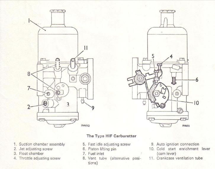
As a matter of interest, where is the normal vacuum orifice take-off for the carp setup?
Ramon
Ramon, thanks for that extract, good work and clearly explained.. it must be if I can understand it  Will give me plenty to do tongiht.
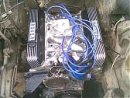
Pocket, yup its a carb so I will block off the vacuum pipe. Its a 3.5 out of a disco but with a 110 land rover intake and twin SU carbs. 9.35 cr but with composite gaskets so thats probably dropped a little.
Looking at the picture of the carbs I'm a little confused (easily done) its all up and running and seems hunky dorey. However a lot of that carb looks upside down to mine. Fuel inlet is on the bottom of mine, and the breather intake is at the top, also thankfully the vacuum inlet is also at the top probably a different model of carb I guess but it seems a lot more sensible with the vacuum take off on the top
Chees guys!
Pocket, yup its a carb so I will block off the vacuum pipe. Its a 3.5 out of a disco but with a 110 land rover intake and twin SU carbs. 9.35 cr but with composite gaskets so thats probably dropped a little.
Looking at the picture of the carbs I'm a little confused (easily done) its all up and running and seems hunky dorey. However a lot of that carb looks upside down to mine. Fuel inlet is on the bottom of mine, and the breather intake is at the top, also thankfully the vacuum inlet is also at the top
Chees guys!
-
Pocket rocket
- Getting There
- Posts: 256
- Joined: Sun Nov 19, 2006 1:08 am
- Location: Hawkinge, Kent
 [/img]
Well setting the timing didn't go that well. I startecd her up and disconnected the vacuum advance, I also blocked the vacuum port on the carb so it wouldn't leak.
Get the timing light out and started rtatting the dizzy to see what effect it had. I moved it to around 4 degrees and it sounded quite a bit rougher so went back to my start point and it died
I tried to start it up agin and didn't get anywhere.. it sounded like it was only firing on one or two cylinders. I took the dizzy cap off and it looks like the rotor arms hit the contacts and has snapped some of the plastic bits off inside. The piece of metal on top of the rotor arm is also a little loose.
So new cap and rotor arm. Im guessing the cap was a loose fit and got clattered when I was poking about. I have an opus dizzy, were there different caps for the different dizzy's?
This was a generic blue cap that I had with it when I bought it.. So probably should have replaced it anyhow!
-
ramon alban
- Knows His Stuff
- Posts: 667
- Joined: Fri Nov 17, 2006 11:22 pm
- Location: Bedford UK
- Contact:
