flapper relays / diodes

General Chat About Electrics, And Ignition Systems.

Moderator: phpBB2 - Administrators

ramon alban
Knows His Stuff
Knows His Stuff
Posts: 667
Joined: Fri Nov 17, 2006 11:22 pm
Location: Bedford UK
Contact:

Post by ramon alban »

sowen wrote: The engine was coughing every few revolutions, so I measured the voltage on either side of the inline resistor to the ecu, 0.5v on the ecu side, and 7v on the coil negative side. So out with the resistor and hey presto, a running engine :D

After replacing the brand spanking new lucas relays with old bosch relays the engine was showing signs of life? So I guess I just had a bad combination of parts and no spares to begin with.
Simon, I may be wrong, but according to my research the inline resistor has two functions.

1 As a voltage drop input component to ensure the ECU receives the correct level of pulsed input voltage.

2 Protect the ECU from any excess induced voltage that might otherwise occur at the ignition coil.

Induced voltages or back emf's are generated when voltage is switched to a coil and these can be higher than the switched input. They may not be significant with regard to the switched function but if fed to an electronic component there is a possibility of unwanted high voltage spikes doing damage.

Prudence would say that there needs to be protection. perhaps by limiting the input voltage or by suppressing the voltage spikes with a capacitor. A suppressor.

If you have managed to measure any meaningful voltage with the engine running then bear in mind the volmeter can only read an average of the pulses making up the voltage.

On the other hand if the voltage was measured with ignition on and engine not running then you had a figure of 0.5 volts at the ECU and 7 volts at the coil -ve.

Removing the inline resistor will allow that 7 volts directly to the ECU. Lets hope that the ECU input can stand that much. 14 times the original voltage, so 14 times the induced voltage or voltage spikes.

Rover put that resistor in for a reason. Somehow by taking it out, you have managed to induce the ECU to run the engine, but apparantly not perfect yet.

Something else is going on, and it would seem to me to be risky.

Urban legend may tell us that enthusiasts have run their Rover Efi systems perfectly well without the in-line resistor in circuit.

Hmmnnn!! I would think carefully beforehand, or get a technical input that turns the afore-mentioned stuff into BS.


sowen
Getting There
Getting There
Posts: 248
Joined: Sat Feb 24, 2007 10:10 am
Location: Warwickshire

Post by sowen »

Thanks Ramon. I understand what you mean, I've now got 6 ecu's to play with so I gave it a go, and it worked. There are quite a few niggles around the ignition system now I have efi which weren't there with the carbs. I'm going to rewire the original series land rover ignition system so it can handle the extra load now going through it, among many other jobs which have been shown up with todays success.

I measured the voltages with the engine running with a digital multimeter, which obviously cannot show the true pulses, but gave enough of a clue to remove the resistor. There's still some experimentation to go, as only one of the six ecu's work properly, clearly showing I have some other hidden problems that need sorting, but it runs again so I'm happy :P

Simon
1972 Rover 2000TC M16 turbo
1975 Land Rover OM606 diesel
1984 Rover SD1 3500 Megasquirt powered
sowen
Getting There
Getting There
Posts: 248
Joined: Sat Feb 24, 2007 10:10 am
Location: Warwickshire

Post by sowen »

The inline resistor is now back in place, I had to run the entire ignition system off a big relay to get it running properly, the misfire I had seems to have gone now and it runs much smoother.

Simon
1972 Rover 2000TC M16 turbo
1975 Land Rover OM606 diesel
1984 Rover SD1 3500 Megasquirt powered
mrcheese
Newbie
Newbie
Posts: 47
Joined: Fri May 18, 2007 2:29 pm

Post by mrcheese »

I think the reason for the resistor is to block any false pulses reaching the ECU rather than providing any protection. These false signals are noise and are much lower level than the pulse from the negative of the coil. I read this somewhere, but can't find the document at the moment.

Paul.
ramon alban
Knows His Stuff
Knows His Stuff
Posts: 667
Joined: Fri Nov 17, 2006 11:22 pm
Location: Bedford UK
Contact:

Post by ramon alban »

mrcheese wrote:I think the reason for the resistor is to block any false pulses reaching the ECU rather than providing any protection. These false signals are noise and are much lower level than the pulse from the negative of the coil. I read this somewhere, but can't find the document at the moment.

Paul.
Hi Paul, Thats an interesting observation. A resistor cannot "block" pulses as such, because its not an active component, but it would attenuate (reduce) them, it being effectively part of a potential divider in series with the input impedance (resistance) of the ECU at pin 1

So the 6.8 kohm resistor connects to the effective input resistance which connects to ground. The ECU therfore see a lower level of input pulse AND interferance (noise, whatever) at Pin 1.

Whereas my interpetation in my point # 2 was not disimilar - ie:

Protect the ECU from any excess induced voltage that might otherwise occur at the ignition coil.

What you are saying is, its not PROTECTION as such, but limiting of the same induced input noise to prevent false engine speed signal readings.

Either way it would be unwise to run the system with the resistor removed, but not fatal to the ECU according to your discovery.

If you find the source of your information please let me know and I will adjust my documents.

Its the same with all my other stuff. If there are errors and/or omissions its best if they can be eliminated.
User avatar
ChrisJC
Top Dog
Top Dog
Posts: 5077
Joined: Mon Nov 20, 2006 1:13 pm
Location: Northants / Cambs
Contact:

Post by ChrisJC »

We've had this conversation before.

I can't remember the exact details now, but I took apart an ECU and traced the input circuit for the coil -ve feed. At the time I concluded that the resistor didn't do anything useful, so I've been running without it for 27000 miles.

The input protection circuit is very comprehensive (because as Ramon says you get massive - 400V - voltage spikes every time there's a spark).

So I wonder if it's more an electromagnetic interference device, to stop the coil to ecu feed radiating like an aerial and messing up the radio. Otherwise the resistor value inside the ECU could just have been changed and the in-line resistor done away with.

Chris.
--
Series IIA 4.6 V8
R/R P38 4.6 V8
R/R L405 4.4 SDV8
ramon alban
Knows His Stuff
Knows His Stuff
Posts: 667
Joined: Fri Nov 17, 2006 11:22 pm
Location: Bedford UK
Contact:

Post by ramon alban »

ChrisJC wrote:We've had this conversation before.

I can't remember the exact details now, but I took apart an ECU and traced the input circuit for the coil -ve feed. At the time I concluded that the resistor didn't do anything useful, so I've been running without it for 27000 miles.

The input protection circuit is very comprehensive (because as Ramon says you get massive - 400V - voltage spikes every time there's a spark).

So I wonder if it's more an electromagnetic interference device, to stop the coil to ecu feed radiating like an aerial and messing up the radio. Otherwise the resistor value inside the ECU could just have been changed and the in-line resistor done away with.

Chris.
Chris, A passive resistor, by itself would not stop electromagnetic interferance, that would take a selection of coils and capacitors, which are probably in the very comprehensive ccts you looked at and the external resistor is simple an extention of that

HOWEVER. How does this sound??

Given your input it may simply be to protect the wiring and the amplifier from a short circuit on the Efi loom or beyond, in the remote possibility that there is a short to earth between the inline resistor and the ECU pin 1.

If that happened with the resistor in = no problemo.

BUT with the resistor out = expensive dark brown smell.

If that were right then it may be risky to run without it, which really means that in the 27000 miles. you have not had a problem YET.

If you system runs ok with it IN, I would put it back!!
User avatar
ChrisJC
Top Dog
Top Dog
Posts: 5077
Joined: Mon Nov 20, 2006 1:13 pm
Location: Northants / Cambs
Contact:

Post by ChrisJC »

ramon alban wrote:
Given your input it may simply be to protect the wiring and the amplifier from a short circuit on the Efi loom or beyond, in the remote possibility that there is a short to earth between the inline resistor and the ECU pin 1.

If that happened with the resistor in = no problemo.

BUT with the resistor out = expensive dark brown smell.
The circuit is definitely an input circuit, so connecting to either gnd or +12v is no problem. I couldn't see any way to damage the ECU by abusing the input. After all, the coil -ve is shorted to ground then injected with a massive spike, I can't think of anything much worse.
ramon alban wrote: If that were right then it may be risky to run without it, which really means that in the 27000 miles. you have not had a problem YET.

If you system runs ok with it IN, I would put it back!!
:twisted: Nope! I'll put my money where my mouth is.....

Chris.
--
Series IIA 4.6 V8
R/R P38 4.6 V8
R/R L405 4.4 SDV8
User avatar
ChrisJC
Top Dog
Top Dog
Posts: 5077
Joined: Mon Nov 20, 2006 1:13 pm
Location: Northants / Cambs
Contact:

Post by ChrisJC »

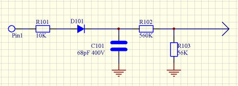
I thought I'd put this one to rest. I opened up a spare ECU this evening. Here's the circuit:

Image

I can't see for the life of me what putting another 5.6K outside the ECU will do - why not change R101 to 15K?

Chris.
--
Series IIA 4.6 V8
R/R P38 4.6 V8
R/R L405 4.4 SDV8
Post Reply

Return to “Electrical & Ignition Area”