
Newbie post here.
I have a bog standard 3.5 RV8 EFI in an SD1 EFI, so originally using the Lucas flapper injection. I'm now using a MegaSquirt fuel only with great success. Much more grunt - but still needs fine tuning to get the best economy.
I'm going to convert the ignition to the MS too - and although eventually I'll probably go down the EDIS route I'm going to start with a locked dizzy.
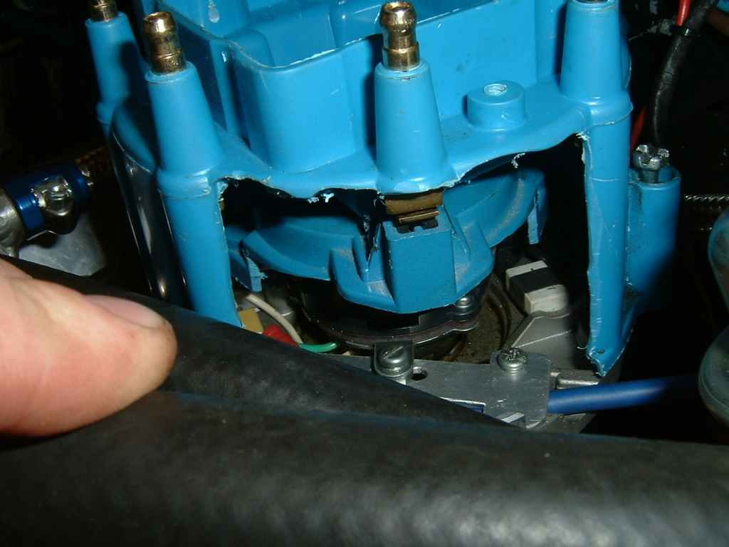
I've got a spare one and have locked up the centrifugal advance and removed the vacuum unit - but am unsure about where to lock the top plate to set the rotor arm/dizzy cap contact relationship. My gut feeling is with the leading edge of the rotor arm just 'touching' the start of the contact at the firing point to allow for the mapped advance. But I'm having some trouble getting my head round this one - and the danger of cross-firing is very real.
I've fitted a home made hall effect sensor to replace the original VR one - so the trigger point is clearly defined as it will trigger at zero speed. And I've cut a hole in a spare cap so I can see where things happen.
I'd be very grateful for any pointers from someone who has done this conversion.
I'd also like to have a look at any MSQ or basic files known to work well with this version of the RV8 - most I can find seem to be for other or modified ones
I'm running MSII Rev 2.89000. DIY built MS.
Locking a distribtor for use with a MegaSquirt
Moderator: phpBB2 - Administrators
Locking a distribtor for use with a MegaSquirt
Dave
London SW
Rover SD1 VDP EFI
MegaSquirt2 V3
EDIS8
Tech Edge 2Y
London SW
Rover SD1 VDP EFI
MegaSquirt2 V3
EDIS8
Tech Edge 2Y

ask Phil himself if he has done it to that dizzy mate,
he is a member of this forum daxtojeiro
he is a member of this forum daxtojeiro
Regards Tony C (COOPS)

MS2 V3.57 Ecu mapable efi and wasted spark ignition.
Procharger D1SC supercharger and Cossie RS500 Intercooler @ 14psi of Boost. 416 RWHP, (boost leak)
Forged 4.8 V8 kitted out with the dogs Cajones of parts.
Sponsored by: www.v8performanceparts.co.uk, www.interpart.biz, www.caprisport.com & www.baileyperformance.co.uk
-
stevieturbo
- Forum Contributor

- Posts: 3979
- Joined: Sat Nov 18, 2006 6:22 pm
- Location: Northern Ireland
Think it is rather important to get the rotor arm/cap phasing right to prevent cross firing. On an eight cylinder one there isn't much tolerance.stevieturbo wrote:its no big deal.
Just weld up the advance mech. Rotor arm position does of course matter with regards to it needs pointing at the post in the cap. But you can rotate the dizzy anywhere you want to align the rotor arm.
The trigger is also in the dizzy, so turning the dizzy will alter the timing - but not the phasing. The top plate has to be turned to do that. I think
Dave
London SW
Rover SD1 VDP EFI
MegaSquirt2 V3
EDIS8
Tech Edge 2Y
London SW
Rover SD1 VDP EFI
MegaSquirt2 V3
EDIS8
Tech Edge 2Y
-
stevieturbo
- Forum Contributor
- Posts: 3979
- Joined: Sat Nov 18, 2006 6:22 pm
- Location: Northern Ireland
-
daxtojeiro

- Forum Sponsor

- Posts: 330
- Joined: Sat Nov 25, 2006 12:10 am
- Location: Norwich UK
- Contact:
Hi,
theres also this PDF file I recently added:
http://www.extraefi.co.uk/Drawings/PDF_ ... _dizzy.pdf
There will soon be one to show you how to turn it into a cam signal for seq fuel as I've just completed it on my RV8
Phil
theres also this PDF file I recently added:
http://www.extraefi.co.uk/Drawings/PDF_ ... _dizzy.pdf
There will soon be one to show you how to turn it into a cam signal for seq fuel as I've just completed it on my RV8
Phil

http://www.extraefi.co.uk/cobra/accobra.htm SuperCharged 5325cc V8 Cobra Replica (Full sequential Fuel and Ignition MS3 management)
Thanks Phil. That's what I've done to my DLM dizzy. But having read about so many problems setting up a VR sensor with MS in the various groups I decided to change it to a hall effect one. I used an Allegro gear one and fixed it to the original base of the VR one after removing the coil and coil core piece. On bench tests it's giving a solid trigger from 0 - 4000 dizzy RPM.daxtojeiro wrote:Hi,
theres also this PDF file I recently added:
http://www.extraefi.co.uk/Drawings/PDF_ ... _dizzy.pdf
There will soon be one to show you how to turn it into a cam signal for seq fuel as I've just completed it on my RV8
Phil
Dave
London SW
Rover SD1 VDP EFI
MegaSquirt2 V3
EDIS8
Tech Edge 2Y
London SW
Rover SD1 VDP EFI
MegaSquirt2 V3
EDIS8
Tech Edge 2Y
Right. As I said I'm having difficulty in getting my head round all the variables.stevieturbo wrote:Yes, as I said it does matter where it points, but its easy to swing the dizzy wherever you want so that it works without crossfire issues.
Just re-adjust the TDC pickup position within the software after the rotor arm/dizzy is positioned where you want it
As I said, it shouldnt be a big deal.
My initial thought was I'd have to adjust the trigger physical position relative to the rotor arm by moving the top plate it's mounted on then locking that, to get the phasing correct. Based on having no offset in MS for the timing. But you're saying the offset will do effectively the same?
I've asked about this elsewhere - and had so many opposite answers.
But here I seem to be getting advice from those who've got practical experience of the problems.
Dave
London SW
Rover SD1 VDP EFI
MegaSquirt2 V3
EDIS8
Tech Edge 2Y
London SW
Rover SD1 VDP EFI
MegaSquirt2 V3
EDIS8
Tech Edge 2Y
-
stevieturbo
- Forum Contributor
- Posts: 3979
- Joined: Sat Nov 18, 2006 6:22 pm
- Location: Northern Ireland
As Ive little experience with MS. I can only assume you can electronically set the TDC position within the software like every other ecu, and that relative TDC position in a mechanical sense isnt fixed rigidly to being in a certain place.
Im sure Phil will clarify if its possilbe or not. I'd be very surprised if it isnt.
Im sure Phil will clarify if its possilbe or not. I'd be very surprised if it isnt.
Yes you can. But in case it's not clear, my problem is making sure the rotor arm is still lined up with the contact on the dizzy cap. With centrifugal advance this isn't a problem, since the rotor tracks the advance. And this gives the major part of the ignition advance. With vacuum control the trigger is shifted relative to the rotor - so the rotor has a wider contact to accommodate this. But once you lock the dizzy and do it in software it becomes important to phase the rotor to cap contact correctly to prevent misfire.stevieturbo wrote:As Ive little experience with MS. I can only assume you can electronically set the TDC position within the software like every other ecu, and that relative TDC position in a mechanical sense isnt fixed rigidly to being in a certain place.
Im sure Phil will clarify if its possilbe or not. I'd be very surprised if it isnt.
Dave
London SW
Rover SD1 VDP EFI
MegaSquirt2 V3
EDIS8
Tech Edge 2Y
London SW
Rover SD1 VDP EFI
MegaSquirt2 V3
EDIS8
Tech Edge 2Y
-
stevieturbo
- Forum Contributor
- Posts: 3979
- Joined: Sat Nov 18, 2006 6:22 pm
- Location: Northern Ireland
But as Ive said, you can position the dizzy anywhere you want so the rotor arm is best positioned to prevent tracking. It will be a compromise, but still perfectly do-able. Ive done it before, whilst also using a Crane CDI ignition system, and never had any crossfire problems.
It isnt really an issue, unless you are running extreme ranges of advance.
if it does become a major issue, just install a crank based trigger like 36-1 instead and use that instead of the dizzy. then you can leave the advance mech in place so the rotor arm does track better.
It isnt really an issue, unless you are running extreme ranges of advance.
if it does become a major issue, just install a crank based trigger like 36-1 instead and use that instead of the dizzy. then you can leave the advance mech in place so the rotor arm does track better.
Am I missing something here, isn't it quite simple to set up, once locked up you align the post on the dizzy cap with trailing edge of the rotor arm in the most retarded, ie static condition. The MS is only going to advance timing from the static position, (nominally 10 degrees) max advance of the rover is about 34 degrees of crank so the MS adds 30 degrees of advance, the distributor rotates at half engine revs so from static setting the advance aroung the rotor arm is 15 degrees, the "contact" (yes I know it doesn't touch) on rotor arm covers about 20 degrees of ark so no risk of cross fire as the next post is another 30 degrees away  .
.
Best regards
Mike
Best regards
Mike
poppet valves rule!
You do have two alignments to achieve- one is making sure the trigger is at the correct angle and the other is ensuring the rotor is where you want it.
I set the engine at 28' btdc - which is what I considered to be the "average" advance - then turned the dizzy around until my rotor was aligned in the centre of the tower. (so 12' would be a bit one way and my max advance would be a bit the other way). http://www.mez.co.uk/dcam/DSCF0330.JPG
Then I made a bracket that replaced the old vacuum advance unit which locked the pickup at my desired trigger location (50' btdc in my application)
http://www.mez.co.uk/ms9.html (all very old an out of date - I run edis now)
