Uncobra, the V8 FrankenHealey
Moderator: phpBB2 - Administrators
-
ihatesissycars

- Forum Contributor

- Posts: 938
- Joined: Sat Nov 18, 2006 8:22 am
- Location: Aaaaaaampshire!
-
kev_the_mole
- Forum Contributor
- Posts: 1022
- Joined: Sat Nov 18, 2006 9:41 pm
- Location: Las Islas Purbequias
That's the plan but probably in stages. As it hasn't been driven for 13 months all I want to do for this summer is get it on the road with the current carburation.
This winter's project is to go fuel injection. Wiring will be put in this month for a high pressure pump in the boot and I've got to choose between Megasquirt, Emerald or Vems for the ECU (difficult) and I'll go with a 4-barrel throttle body as a direct replacement for the Holley.
As I've got access to CNC mills and lathes I'm looking at the feasibility of making my own roller throttle bodies as I think that 8 trumpets poking up from the top of a V8 is one of the best automotive sights ever!
BUT it's got to be finished and put on the road first......
It's an engine Jim.....but not as we know it
If you do decide to go this route, roller throttles and individual throttle bodies get in touch, this is the way I want to go for my chevy, we could split the development costs/effort, I have the manifold sections drawn up and will be making the plugs up for the castings for the manifold this summer, but can still change design at this stage to fit around others ideas.
Mike
Mike
poppet valves rule!
-
kev_the_mole
- Forum Contributor
- Posts: 1022
- Joined: Sat Nov 18, 2006 9:41 pm
- Location: Las Islas Purbequias
-
kev_the_mole
- Forum Contributor
- Posts: 1022
- Joined: Sat Nov 18, 2006 9:41 pm
- Location: Las Islas Purbequias
.... an occasional Healey project.
Turning to the lighting and signalling I have a bit of a problem. Being a 1954 model I uprated the headlights to halogen and the very small front side lights / indicators should be OK but at the back it's a disaster for modern road conditions. The rear side / stop / indicator lights are just one small 45mm red light incorporating all three functions and so low on the car to be not clever at all.
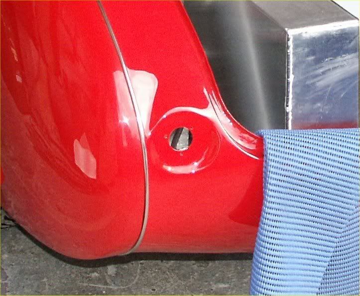
You can see that the flat area to take the housing is about 75mm diameter so I started looking for a ready made solution. Most of them were either waaaay too deep or only two function so I decided to make my own.
20 minutes with the CNC mill and some obscured, mirror and coloured Perspex got me to here. Obviously the the amber section is too small and will be increased to 40mm diameter.
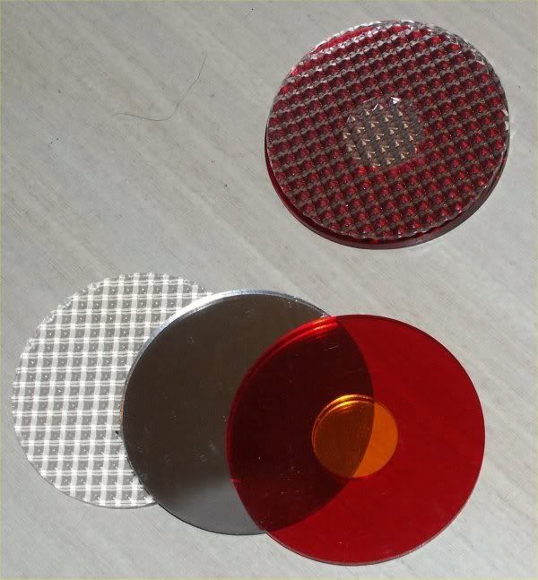
Now what to use for illumination? Well I definitely can't get 2 /3 bulbs into a housing without drilling holes in the ally shroud or making the housing deep so it had to be LED's.
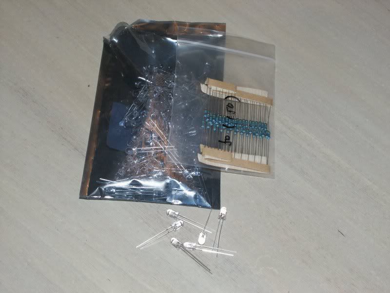
An evening with Google got me 150 LED's and the matching resistors posted from Hong Kong in 4 days. A quick visit to Maplins for some breadboard and to W H Smiths for some sophisticated drawing equipment and you get the picture below.
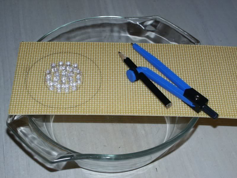
There's 21 LED's in the central amber indicator section (yet to be soldered up) and there'll one ring each of 18 and 24 LED's for side and stop under the red Perspex. These 3.3Volt, 30000 Mcd LED's need to be in groups of three with a resistor.
As there are about 200 soldered joints in both lights this will be an occasional report.
Turning to the lighting and signalling I have a bit of a problem. Being a 1954 model I uprated the headlights to halogen and the very small front side lights / indicators should be OK but at the back it's a disaster for modern road conditions. The rear side / stop / indicator lights are just one small 45mm red light incorporating all three functions
You can see that the flat area to take the housing is about 75mm diameter so I started looking for a ready made solution. Most of them were either waaaay too deep or only two function so I decided to make my own.
20 minutes with the CNC mill and some obscured, mirror and coloured Perspex got me to here. Obviously the the amber section is too small and will be increased to 40mm diameter.
Now what to use for illumination? Well I definitely can't get 2 /3 bulbs into a housing without drilling holes in the ally shroud or making the housing deep so it had to be LED's.
An evening with Google got me 150 LED's and the matching resistors posted from Hong Kong in 4 days. A quick visit to Maplins for some breadboard and to W H Smiths for some sophisticated drawing equipment
There's 21 LED's in the central amber indicator section (yet to be soldered up) and there'll one ring each of 18 and 24 LED's for side and stop under the red Perspex. These 3.3Volt, 30000 Mcd LED's need to be in groups of three with a resistor.
As there are about 200 soldered joints in both lights this will be an occasional report.
It's an engine Jim.....but not as we know it
-
kev_the_mole
- Forum Contributor
- Posts: 1022
- Joined: Sat Nov 18, 2006 9:41 pm
- Location: Las Islas Purbequias


Hi Ian
any idea of the center spacing for the roller throttles yet? I'll draw up the manifolds to match if you have a start of a design, and look at casting costs. Are your heads vortec or non vortec ports? standard or aftermarket? I'm using RHS 235 cc inlet port heads non raised port heads non vortec inlet shape and spacing. Over next winter is good timing for me.
Mike
poppet valves rule!
-
kev_the_mole
- Forum Contributor
- Posts: 1022
- Joined: Sat Nov 18, 2006 9:41 pm
- Location: Las Islas Purbequias
Marki,
the manufacturers specifically state that they must be used with a resistor and the optimum number is three so I just followed their advice. They state with 3.3 volt LEDs and 13.6 volts nominal when charging if you use 4 without a resistor you stand a much greater chance of them burning out. If you use 5 then they are working below their rated light output voltage and will run dim. If you use one LED to a (big) resistor then you run into heat dump problems.
I'll just suck it and see.
Cheers,
Ian
It's an engine Jim.....but not as we know it
-
kev_the_mole
- Forum Contributor
- Posts: 1022
- Joined: Sat Nov 18, 2006 9:41 pm
- Location: Las Islas Purbequias
Mike,
what centres do you need? If it's feasible then most of the machining is parameterised and small differences in centres could be accomodated. I was thinking of the same spacing as IDA's as I know someone with a redundant manifold!!!
My heads are non-Vortec and are just ported and matched standard heads. Another thing to upgrade over time!
Ian
It's an engine Jim.....but not as we know it
-
kev_the_mole
- Forum Contributor
- Posts: 1022
- Joined: Sat Nov 18, 2006 9:41 pm
- Location: Las Islas Purbequias
...never ever choose to skim and recondition a bonnet with louvres. There's 56 of them louvres below and they made the job touch and go at times and about twice as expensive 
but it does look nice.
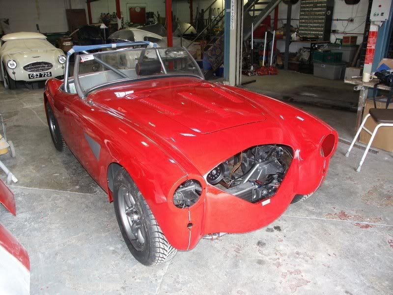
lurking in the background under the cover is a Healey 100S, one of only 50 made. Very upmarket company for the old nail
but it does look nice.
lurking in the background under the cover is a Healey 100S, one of only 50 made. Very upmarket company for the old nail
It's an engine Jim.....but not as we know it
Hi Ian
my original plan was to go for 60mm (2 3/8") throttle bodies on 80 to 85mm centers to look like the Hilborn set up from a distance. Using barrel throttles in pairs in line with the heads. The manifold is easier to design like this in that it is more of a straight shot at the back of the inlet valve but still has the throttles far enough apart to be able to get a good seal between them.
To be honest I am not tied to anything as yet, as I was planning on having the manifolds cast as 4 pairs and using an "sb2 style" water manifold/vally cover, then getting the throttle bodies machined up to match and sandwiching an ally plate between the manifolds and the throttle bodies to hold the whole lot together and give me somthing to build a throttle linkage in. Shouldn't actually matter which style of head is used as it should just be a case of re drilling the bolt holes and making sure there in enough cast metal to port match.
Mike
poppet valves rule!
-
kev_the_mole
- Forum Contributor
- Posts: 1022
- Joined: Sat Nov 18, 2006 9:41 pm
- Location: Las Islas Purbequias
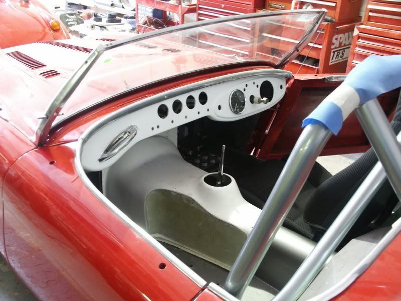
...not much been going on recently as awaiting the new ally rad but we have been having a seat beauty contest. The Corbeau seat might fit the car but the rake is too steep to give decent leg room so we needed another seat.
Thanks to the Forum Defender boys we knew that Defender seats were narrow enough and they don't look bad at all
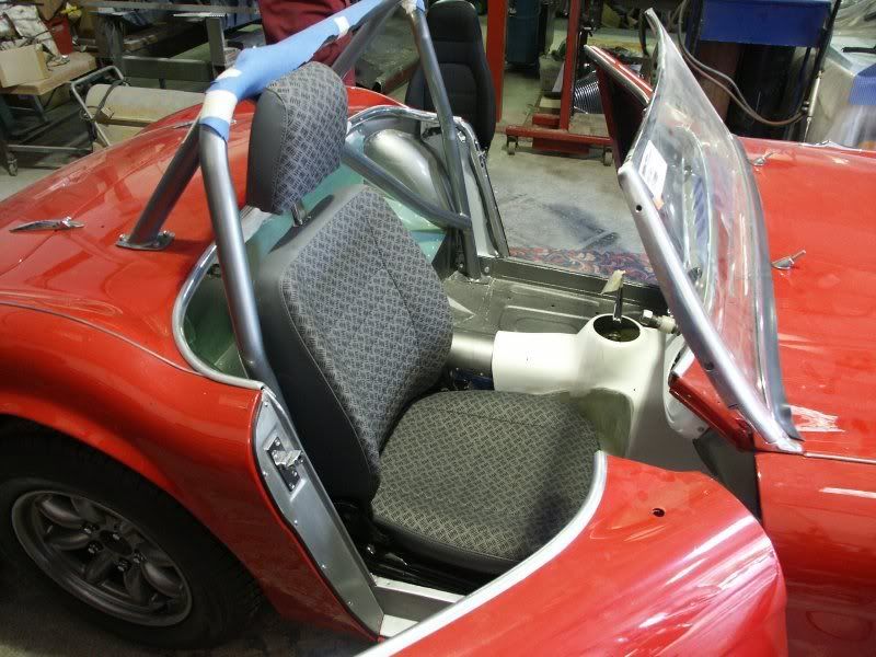
then a suggestion was made to try MX5 seats as fitted in TR6's now. 20 mins later a nice man drove round with a couple to try, and I think we may have a winner
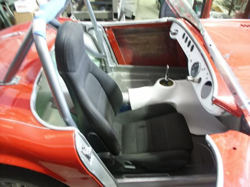
Thanks to the Forum Defender boys we knew that Defender seats were narrow enough and they don't look bad at all
then a suggestion was made to try MX5 seats as fitted in TR6's now. 20 mins later a nice man drove round with a couple to try, and I think we may have a winner
It's an engine Jim.....but not as we know it
-
kev_the_mole
- Forum Contributor
- Posts: 1022
- Joined: Sat Nov 18, 2006 9:41 pm
- Location: Las Islas Purbequias