
(Probably a stupid) MS2Extra Ignition Timing Issue
Moderator: phpBB2 - Administrators
A stim would show up any problems with the ECU pump circuit as it has an LED showing the driver status. In other words, it would go off after a couple of seconds at switch on if the engine isn't running.
I'm willing to bet you have a 'funny' in the wiring - which circuit did you use?
I'm willing to bet you have a 'funny' in the wiring - which circuit did you use?
Dave
London SW
Rover SD1 VDP EFI
MegaSquirt2 V3
EDIS8
Tech Edge 2Y
London SW
Rover SD1 VDP EFI
MegaSquirt2 V3
EDIS8
Tech Edge 2Y
-
richardpope50

- Gold Member

- Posts: 616
- Joined: Thu Jan 28, 2010 12:25 pm
- Location: Horsham, West Sussex
Actually I'm now running a post on MS Forum and also have the chance to try a Stim.
Not quite sure what you mean, Dave, by which circuit but I have followed the MS diagrams I was given. There is a slight discrepancy with other MS circuits on sender earths but I doubt that's it.
No doubt I'll be back!
Not quite sure what you mean, Dave, by which circuit but I have followed the MS diagrams I was given. There is a slight discrepancy with other MS circuits on sender earths but I doubt that's it.
No doubt I'll be back!
Richard.
Dax Rush 5.0l TVR V8, EFI with Megasquirt ECU and wasted spark, Racelogic Traction Control and Quaife LSD ....... Now nut and bolt restoring a TR6
Dax Rush 5.0l TVR V8, EFI with Megasquirt ECU and wasted spark, Racelogic Traction Control and Quaife LSD ....... Now nut and bolt restoring a TR6
-
richardpope50
- Gold Member
- Posts: 616
- Joined: Thu Jan 28, 2010 12:25 pm
- Location: Horsham, West Sussex
I'm doing some bench tests and it seems there is an ECU problem but I'll wait until I can use a stim this weekend to confirm. there may be other problems too!
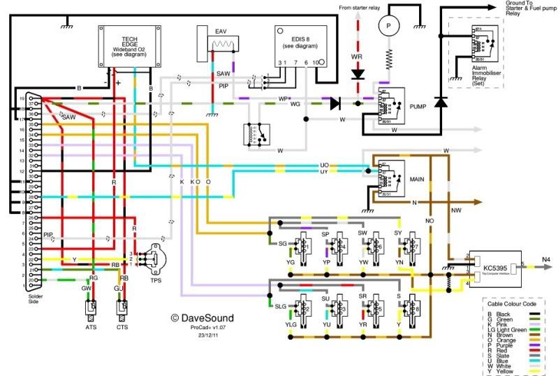
Useful diagram, Dave, but my grounding is different..
My ECU has following four ground wires: Pins 1+2, 7+8, 9>12 and 13>19. All four terimate in one soldered ring connector (to engine block).
Sensor ground wires being Coolant, TPS, Air and AEM Wideband (two wires). These each have soldered ring connectors (to engine block).
I was instructed not to have all ground points at the same engine block point but to keep the ECU grounds away from the sensor. I thus use one of the bolt holes at the rear of each cylinder head - one dvrs side (ECU) and one pass side (sensors).
Having looked at the MS diagrams my set-up differs as they say all sensor grounds to connect to ECU ground. Diagram seems to indicate to connect inside 37 pin plug but this may just mean to same point on block or plug.
I am guessing that there is little difference between mine and MS but there seems a difference with yours.
Richard.
Dax Rush 5.0l TVR V8, EFI with Megasquirt ECU and wasted spark, Racelogic Traction Control and Quaife LSD ....... Now nut and bolt restoring a TR6
Dax Rush 5.0l TVR V8, EFI with Megasquirt ECU and wasted spark, Racelogic Traction Control and Quaife LSD ....... Now nut and bolt restoring a TR6
The actual MS terminals (with the exception of 3,4,5,6) you use for grounds ain't that important as 1-19 all go to the ground plane in the PCB.
However, grounding the sensors to the engine block rather than to the MS simply isn't a good idea - you get high current flow between the block and the MS, due to the injector drive circuits. And the sensors work on tiny currents. That's why they all have individual ground leads rather than simply earthing to the block.
Of course I can't guarantee it will cause problems of any sort - it's simply bad practice.
That's why I asked what diagram you used. The genuine MS one is very clear that the sensor grounds go to the DB37 connector - not the engine block. And if the circuit you're using is wrong there, I wonder what else is?
Dave
London SW
Rover SD1 VDP EFI
MegaSquirt2 V3
EDIS8
Tech Edge 2Y
London SW
Rover SD1 VDP EFI
MegaSquirt2 V3
EDIS8
Tech Edge 2Y
