
Hi Paul,
How big is the gap going to be between the underside of the top of the filter box and the top of the carb?
Cheers,
Pete
Monkey business
Moderator: phpBB2 - Administrators
-
unstable load
- Top Dog

- Posts: 1285
- Joined: Mon May 04, 2009 6:53 am
That is looking really nice, Paul.
Just a thought, though I have absolutely no idea how to even begin working it out...... are you going to have some sort of diffuser at the entrance to the airbox to prevent turbulence in the transition from the side inlets towards the carb?
Or have I just chucked a huge spanner in the works with that question?
Cheers,
John
John
Hi John
No spanner at all mate.
I have been thinking about deflectors over the weekend as I felt that I was losing my way a bit with it all shape wise so have. left it alone for a few days.
There will have to be deflectors and that is pretty simple to sort out within the housing with a few layers of glass and a bit of angling of said plates.
Have made a new template for the housing and am basically going to start the shape again because the glue is throwing the garnet paper off when shaping and it has gone a bit skew whiff so a nice square template and an understanding of how it all should look I can now make it look just right .
You might have picked up on that I am a bit fussy when it comes to doing things on my car and yes I am a sad old git but, that'll do for me" won't do for me when it comes down to it.
cheers
P
No spanner at all mate.
I have been thinking about deflectors over the weekend as I felt that I was losing my way a bit with it all shape wise so have. left it alone for a few days.
There will have to be deflectors and that is pretty simple to sort out within the housing with a few layers of glass and a bit of angling of said plates.
Have made a new template for the housing and am basically going to start the shape again because the glue is throwing the garnet paper off when shaping and it has gone a bit skew whiff so a nice square template and an understanding of how it all should look I can now make it look just right .
You might have picked up on that I am a bit fussy when it comes to doing things on my car
cheers
P

Hi All
Apologies for not replying to Mr Scudderfish and Ged
Guys I dont know why but your posts never showed up on my page here until today so I have not been able to say thank you both for the kind comments
Is there a Gremlin in the works for anyone else?
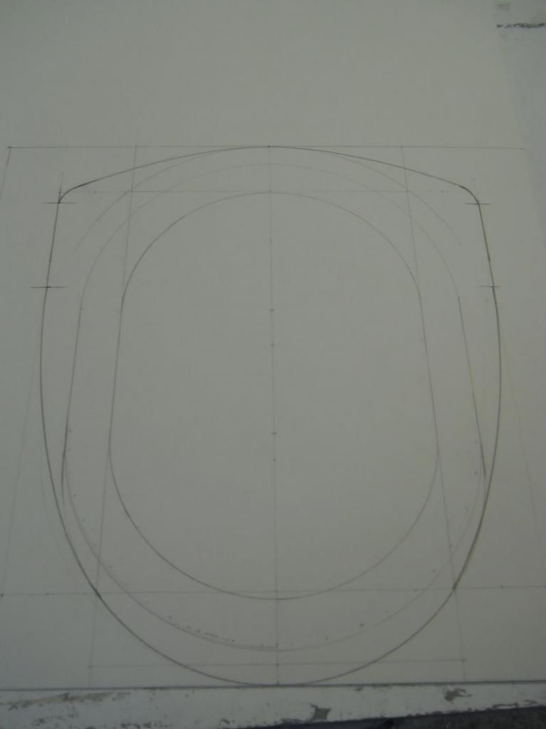
After taking a bit of time out to collect my thoughts and to read what other members thought I decided as already mentioned to redo the whole housing a little bigger and a little wider (thanks Mike) and after getting some poster board a decent compass and some French curves (No not Mrs G's curves and she's not French either) I sat down and drew the new shape out and came up with this.
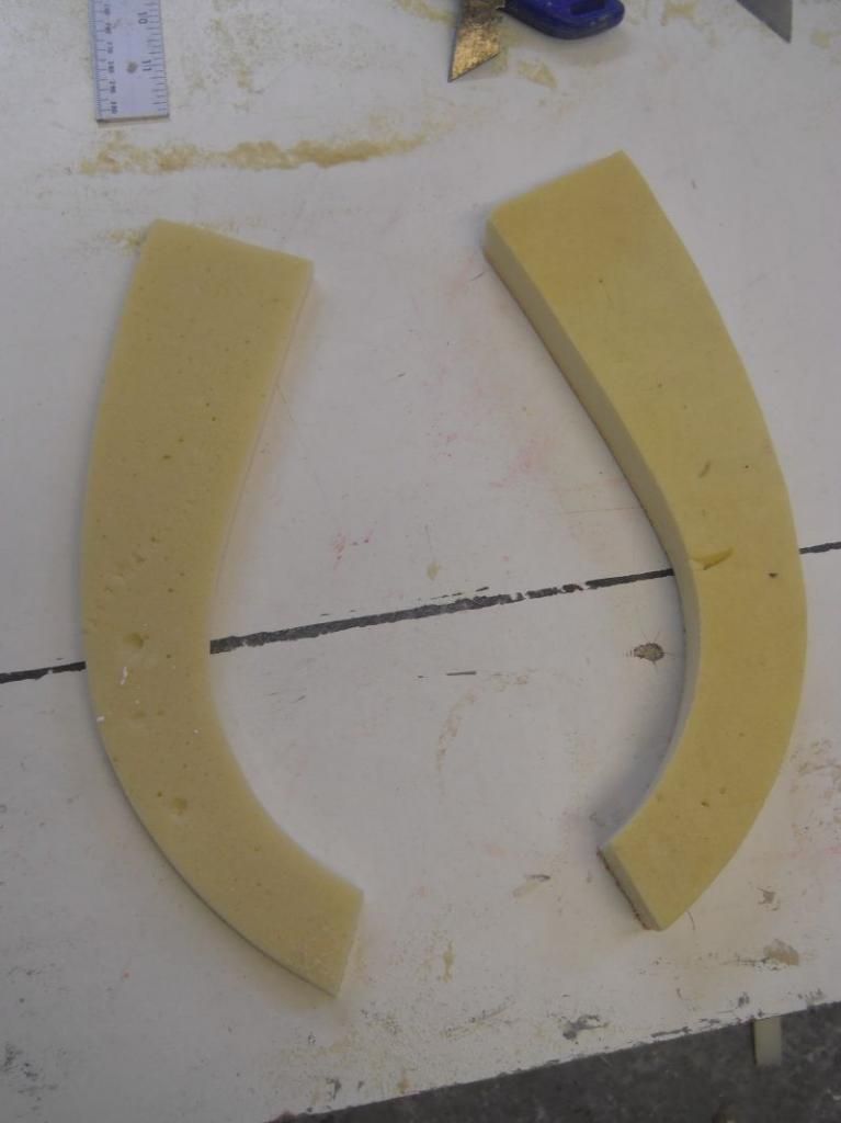
This was then transferred to foam sheets and cut out as before.
All I am worried about at this stage is the outer shape and that it flows in an even way from front to back and can be fairly simple to mould off when that time comes.
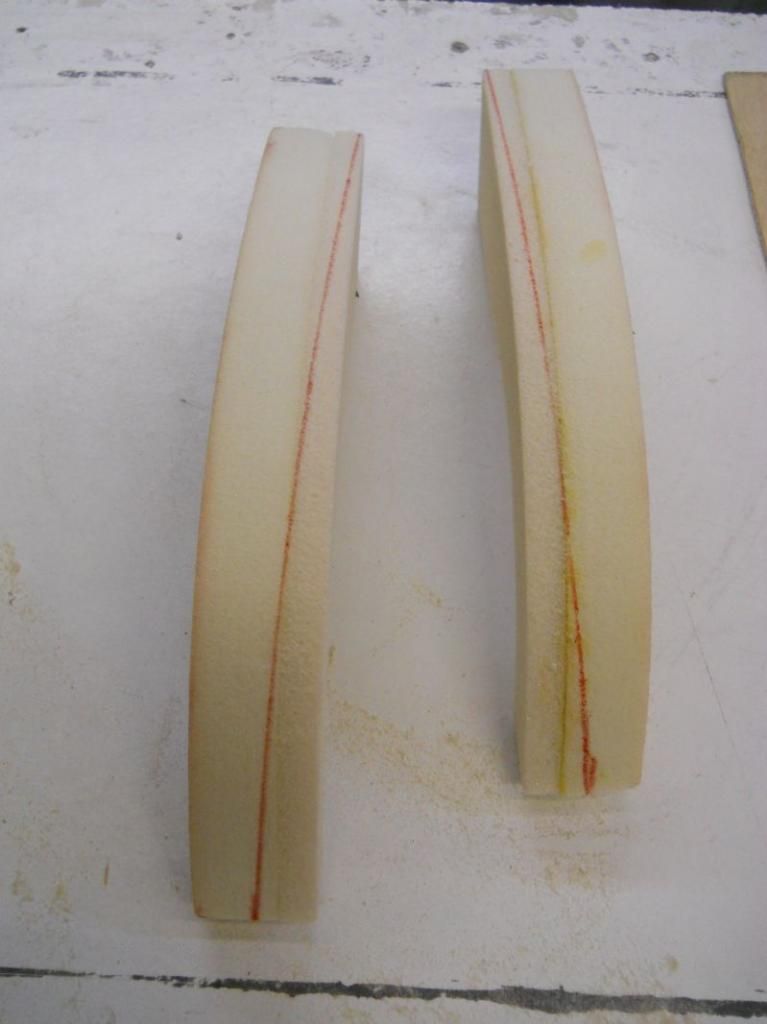
Smaller sections where cut and bonded for the underside front and tapering sections cut and bonded for the back sections.
The lower sections will be bonded once the radii have been formed and all of the cut outs made for the accelerator pump arm and throttle arm to move freely.
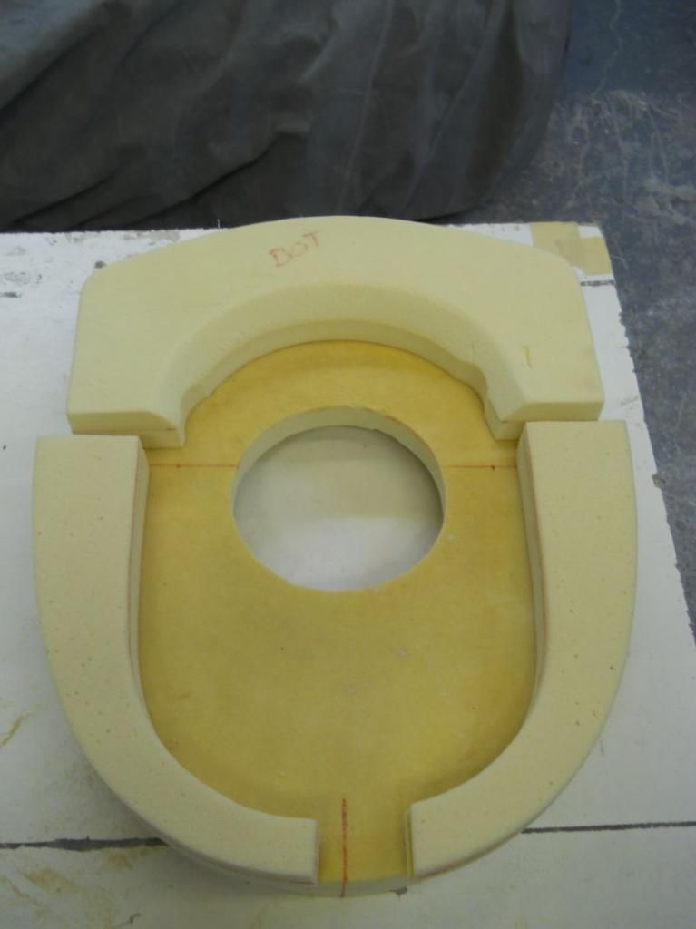
I have offered the new housing up and it looks like this.
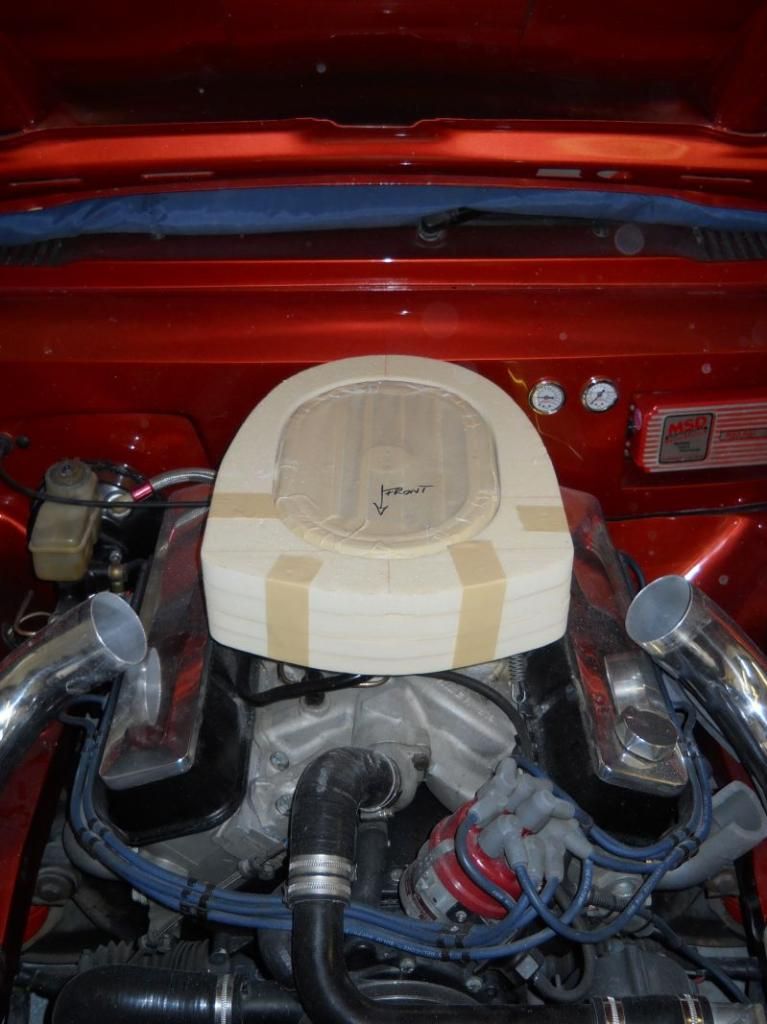
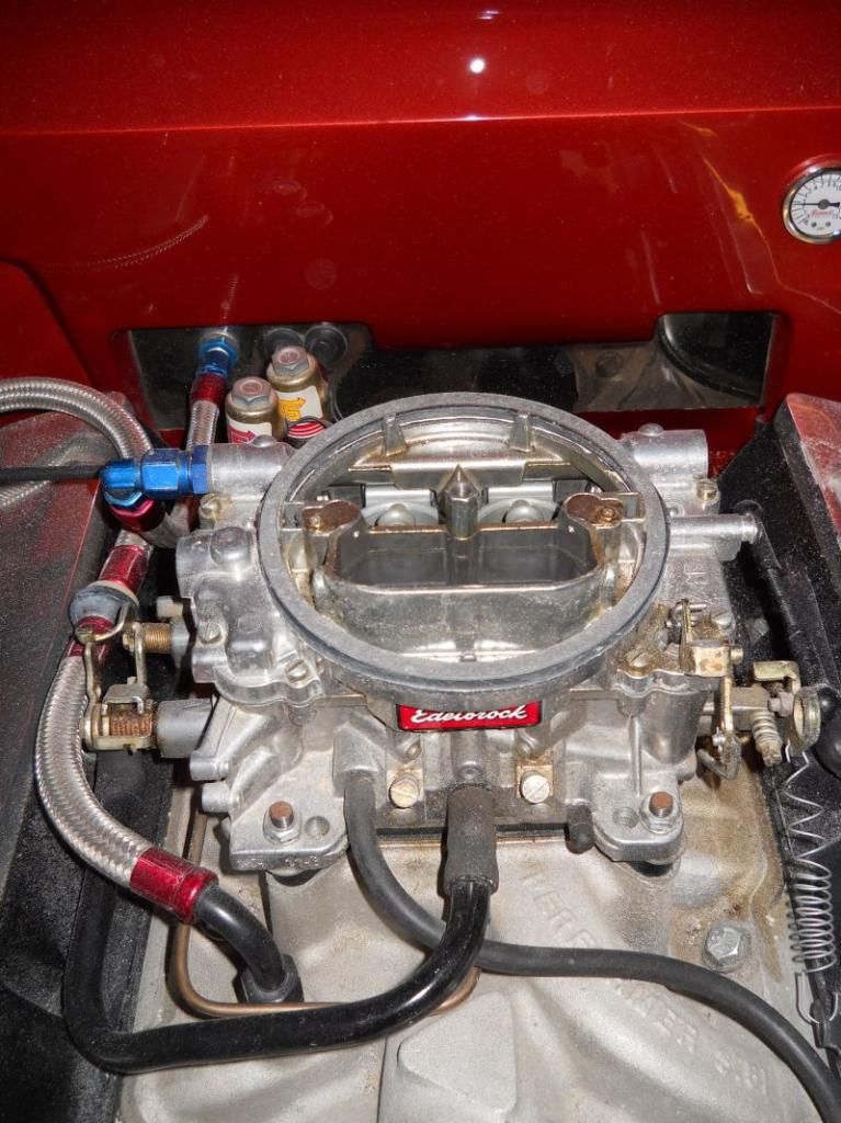
I am thinking of chopping out the choke trumpet on the top of the carb as it is completely redundant now and also making a small stub stack to fit within the filter to help with smooth airflow transition.
Stub stacks generally work best with a couple of inches clearance above them but my way of thinking is that it will do no harm.
If anyone feels the need to correct me on this then please do.
I now have to start thinking a couple of weeks ahead in respect of joining the two halves of the housing together as I cannot glass the whole thing in one hit.
Images of Kiwicar's slingshot front end moulding haunt me to this day
(ha ha)
It seems that there is a fair bit of interest in my malarky judging by the amount of views this project is getting so again thank you to all for your comments and kind words.
Cheers for now
P
Apologies for not replying to Mr Scudderfish and Ged
Guys I dont know why but your posts never showed up on my page here until today so I have not been able to say thank you both for the kind comments
Is there a Gremlin in the works for anyone else?
After taking a bit of time out to collect my thoughts and to read what other members thought I decided as already mentioned to redo the whole housing a little bigger and a little wider (thanks Mike) and after getting some poster board a decent compass and some French curves (No not Mrs G's curves and she's not French either) I sat down and drew the new shape out and came up with this.

This was then transferred to foam sheets and cut out as before.
All I am worried about at this stage is the outer shape and that it flows in an even way from front to back and can be fairly simple to mould off when that time comes.
Smaller sections where cut and bonded for the underside front and tapering sections cut and bonded for the back sections.


The lower sections will be bonded once the radii have been formed and all of the cut outs made for the accelerator pump arm and throttle arm to move freely.
I have offered the new housing up and it looks like this.

I am thinking of chopping out the choke trumpet on the top of the carb as it is completely redundant now and also making a small stub stack to fit within the filter to help with smooth airflow transition.
Stub stacks generally work best with a couple of inches clearance above them but my way of thinking is that it will do no harm.

If anyone feels the need to correct me on this then please do.
I now have to start thinking a couple of weeks ahead in respect of joining the two halves of the housing together as I cannot glass the whole thing in one hit.
Images of Kiwicar's slingshot front end moulding haunt me to this day
(ha ha)
It seems that there is a fair bit of interest in my malarky judging by the amount of views this project is getting so again thank you to all for your comments and kind words.
Cheers for now
P
I cut the choke support off my carb, not sure if this helped or not but the carb still worked afterwards! It did not need re-jetting which I guess implies that it did not make much difference.
With regards to stub stacks I got one from America via Paul, it played havoc with the carb, I could not get it to run right despite a lot of messing about, My LC1 showed bit lean spots as the throttle was being cracked open. I think this was because the small brass tubes which are the air bleed on the primary side of the carb end up in a sort of 'chamber' when the stub stack is fitted. (if you cut the choke horn off you could not use the stub stack that I purchased anyway!)
BTW your second mock up looks really good! I also don't think that you will need any sort of air diffuser because it is not a ram air system, the carb is drawing the air into the air box at the rate at which is requires the air.
Last edited by sidecar on Thu Nov 07, 2013 5:18 pm, edited 1 time in total.
Hello Mr Monkey
did I leave you the F5000 induction scoop the last time I saw you, you could just cut a big hole in the bonnet and have it sticking up in front of you, you know bolt a flat plate to the top of the carb and mount it on that. . . It would look loverrly!
On a more serious note I would not worry too much about defusers, and I think it looks really good now.
Best regards
Mike
poppet valves rule!
Evening All
Had a v long day at work today so not much to show tonight but at least still going forward.
Having made a complete cock of the second housing and getting it all kinds of wrong this time it has to be spot on so more thought and time is going into it and to that end I want to make sure that clearances are good and that nothing from the carb rubs underneath.
Having already sussed out that pump and throttle arms would hit underneath I decided to get rid of the ring at the top of the throttle arm.
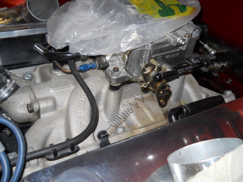
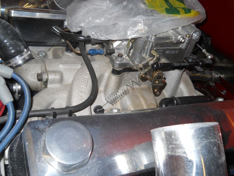
I then scalloped out the lower forward section to give good clearance's and also one of the lower side sections.
This is how that turned out .
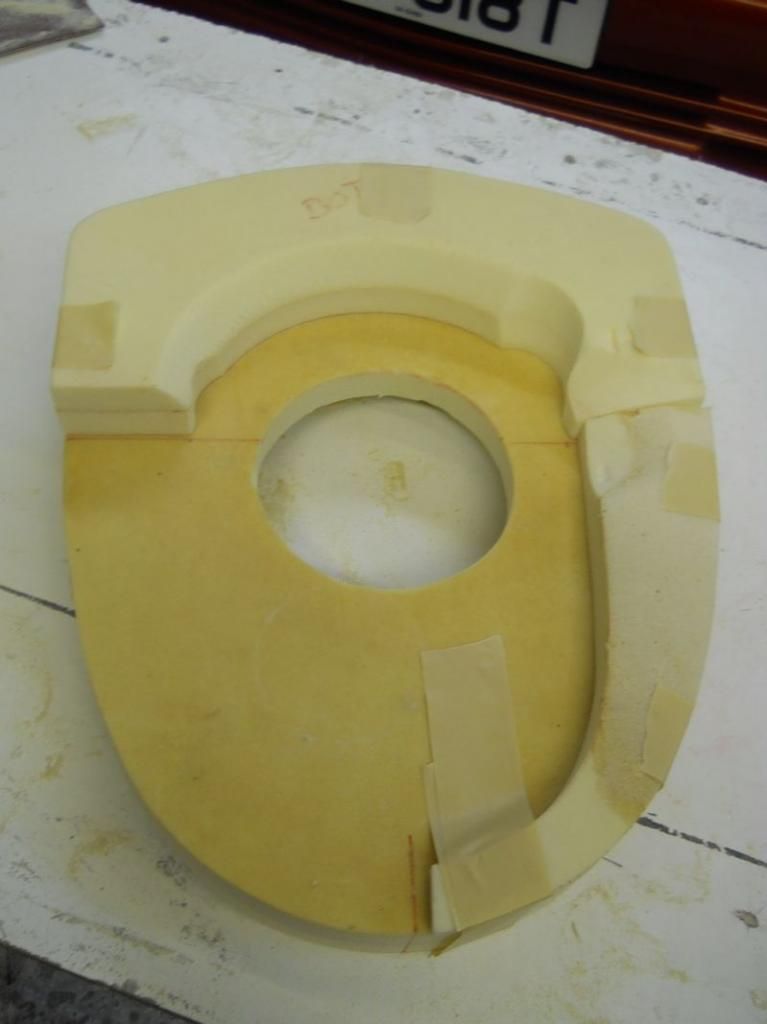
I have glued the front section down this evening and tomorrow I will determine the tube positions and then can glue the side skirts and get them profiled similar to what I had before but hopefully a bit nicer.
It makes a huge difference having a symmetrical shape (DUH) and a clear plan with which to work rather than just stumbling along as I was doing this time last week.
Having never done this kind of project before it is good fun and costing virtually nothing to do.
That's it for now guys
Cheers
P
-
unstable load
- Top Dog
- Posts: 1285
- Joined: Mon May 04, 2009 6:53 am
That lot will look nice finished in body colour Paul 
Perry Stephenson
MGB GT + Rover V8
9.62 @ 137.37mph
Now looking for 8 seconds with a SBC engine
http://www.youtube.com/watch?v=nVscbPHgue0&list=UUqIlXfSAoiZ--GyG4tfRrjw
https://www.youtube.com/watch?v=eg3avnsNKrc&index=2&list=FLqIlXfSAoiZ--GyG4tfRrjw
MGB GT + Rover V8
9.62 @ 137.37mph
Now looking for 8 seconds with a SBC engine
http://www.youtube.com/watch?v=nVscbPHgue0&list=UUqIlXfSAoiZ--GyG4tfRrjw
https://www.youtube.com/watch?v=eg3avnsNKrc&index=2&list=FLqIlXfSAoiZ--GyG4tfRrjw
Hi,
As previously mentioned i have been watching this topic with interest however think i have cheated slightly by purchasing one of these although i have not fitted it yet as due to bonnet clearance issues i still have to shave 3/8" of the bottom. I plan to fit a K&N cone filter via a extension tube near the front to get cool air.
It has a 4" outlet so hoping it will give me the airflow i need (5.0 Rover v8)
Regards
Martyn
