
Hi All
In the final throws of fitting Hotwire to my 90, thought today I'd get it running before finishing off, and no surprise's no start , not even a quick blast from fuel pump, so I am wondering if the ECU is goosed, everything is wired up as per advised on here;
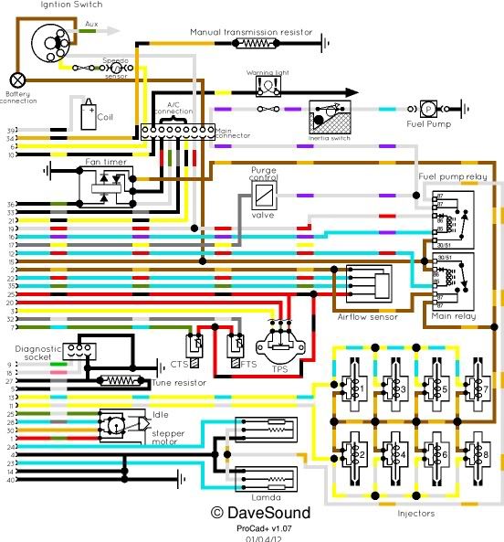
Brown to permanent live feed
White to Ignition 'on' live
White/Purple to fuel pump
With regard to the White wire, it is connected to the White/Red on the EFI loom as there wasn't a white wire, and it appears the White/Red goes to Fuel pump relay so I assume this is correct?
I have live (battery voltage) to all the fuel pump relay terminals except for the White/Purple with the ignition on - is this correct?
There is no relay in the Air-con fan relay base (I assume this doesn't matter)
There is a resistor fitted to the loom as per posts to tell it that there are no Lambda's, although the loom has Lambda connectors - i.e it's off of a @ '92 vehicle which would have had lambda's fitted - do I need to fit anything into those plugs for it to work?
The ECU is from a @ 92 3.9 with Lamda's.
I bought the whole lot off of a guy on Ebay, so no gaurauntee's the ECU or any of it for that matter was working before, unfortunately I don't have a spare one to try.
Greatful for any help/advise where/what to check, have I missed something obvious?
Thank in advance
Regards
Mark
Hotwire ECU Goosed?
Moderator: phpBB2 - Administrators
A pal has just done this to his SD1 and had the wrong relays, and his pump wouldn't run. Worth checking they are the correct Bosch units with diodes as per this circuit:-
The more common 5 pin relays are SPDT types. This injection needs single pole twin output ones. Sadly. both types fit the same base.
The more common 5 pin relays are SPDT types. This injection needs single pole twin output ones. Sadly. both types fit the same base.
Dave
London SW
Rover SD1 VDP EFI
MegaSquirt2 V3
EDIS8
Tech Edge 2Y
London SW
Rover SD1 VDP EFI
MegaSquirt2 V3
EDIS8
Tech Edge 2Y
-
Cappucino-kid
- Newbie

- Posts: 19
- Joined: Tue Feb 08, 2011 8:29 pm
-
Cappucino-kid
- Newbie
- Posts: 19
- Joined: Tue Feb 08, 2011 8:29 pm
According to that diagram, they are the same type of relay contacts wise, but have an internal series diode which the flapper doesn't - it has a separate diode module which likely does the same job.
On the flapper, both relays as supplied are the Bosch twin output types - but the pump only actually needs a simple on/off one, so that can be substituted for the more usual DPDT type. But the main must be the Bosch twin output type.
The flapper Bosch relay is p/n 0332 014 113
According to my pal, the hotwire p/n is 0332 019 151, and they both need to be of this type. However, the new Land Rover relays he bought have a plastic case, so could well have a different part number, but be the same actual relay.
I've seen these older grey Bosch relays with a red stripe across the top - could be these have the diode. They do have the internal wiring stamped on the side and that shows the diode if fitted.
Other way to identify the correct contact layout is there will be two terminals both marked 87. The more common changeover type is marked 87 and 87a.
Think I'll go and hang up my anorak now.
Dave
London SW
Rover SD1 VDP EFI
MegaSquirt2 V3
EDIS8
Tech Edge 2Y
London SW
Rover SD1 VDP EFI
MegaSquirt2 V3
EDIS8
Tech Edge 2Y
-
Cappucino-kid
- Newbie
- Posts: 19
- Joined: Tue Feb 08, 2011 8:29 pm
Ok - no further forward - have the correct relays in place now.
Dave I've noticed if I break the connection, i.e. remove the main relay, or break the main connector plug the Fuel relay clicks and get a split second burst from the fuel pump?
Am I right in thinking that when I switch the ignition on, I should hear a quick burst from the fuel pump (this is not happening at the moment)?
I found as part of the loom supplied a fairly thick black wire, with a thinner black/grey wire along with white/purple + Grey/Yellow (these two have a red plug on the end which I assume is for purge control vavle if fitted). The Black and the Black/Grey have been cut, so not sure what they would have connected to - I have earthed the Black as I am now wondering if it should be earthed on the stud on the rear of the N/S cyclinder head?
There was only one eyelet I found with 3 blacks going to the eyelet which I attached to the stud on the cylinder head, is this correct or should there have been 2 ringlet earth connectors, in which case could it be the black wire mentioned above that should have a ringlet on it?
Any ideas on the Balck/Grey?
Is there anything else obvious I may have missed or that could prevent the fuel pump running?
Thanks in advance for any help.
Regards
Mark
P.S. I haven't tried running yet - maybe tomorrow I will put some fuel in and try it, though I can't see that it will run if the fuel pump isn't priming?
-
Cappucino-kid
- Newbie
- Posts: 19
- Joined: Tue Feb 08, 2011 8:29 pm
