I'm using this to help me wire up my EDIS8 http://www.extraefi.co.uk/Drawings/PDF_ ... Wiring.pdf
and just want to be sure how to connection the shielding on the wire from the ECU and from the VR. Do I connect the blue shielded cable from the ECU AND its shielding to the shielding in the VR cable and then link it all up to pin 7 on the EDIS?
This might help - I redrew the MS diagram to conform with Ford colours and coil connection numbers and how I actually did it.
The VR sensor has the shield connected at the EDIS unit only.
I did the same with the shielded wire for SAW and PIP to the MS ECU. Don't connect the shield at both ends as you might produce a ground loop.
I actually used good quality balanced mic cable for the VR sensor and two mic flexible co-ax for PIP and SAW. The connectors for both those are from Vehicle Wiring Products.
Dave
London SW
Rover SD1 VDP EFI
MegaSquirt2 V3
EDIS8
Tech Edge 2Y
DaveEFI wrote:I actually used good quality balanced mic cable for the VR sensor and two mic flexible co-ax for PIP and SAW. The connectors for both those are from Vehicle Wiring Products.
That diagram makes sense. But my ecu from Phil has a pip (shielded), saw and a blue cable that is also in the shielding with the pip. It looks like Phil's diagram has that blue cable going to pint 7.
seight wrote:That diagram makes sense. But my ecu from Phil has a pip (shielded), saw and a blue cable that is also in the shielding with the pip. It looks like Phil's diagram has that blue cable going to pint 7.
I might email him to double check.
Mike
I may have used a different diagram to start with. But I didn't connect the PIP and SAW screens at the MS end and it works just fine. Of course I could just be lucky.
Dave
London SW
Rover SD1 VDP EFI
MegaSquirt2 V3
EDIS8
Tech Edge 2Y
a quick look on the megajolt site http://www.autosportlabs.net/MJLJ_V4_ve ... tion_guide
shows it going to 7 to join the 2 up vr sensor and wiring back to the megajolt but you can see it all goes to ground i think 7 is just a connection point ?
Interesting - that shows the dedicated shield ground (pin7 on EDIS8) connected to the main EDIS ground, (pin10 on EDIS8). And it sharing the same main ground as the MJ unit.
I'm using a local ground for EDIS - and the +12v is a different circuit from my MS. Basically, both the feeds are the originals for injection and ignition on my SD1. But with heavier gauge cable from ignition switch to EDIS.
No ground connection between the EDIS shield for PIP and SAW and MS. But it seems to work OK.
I'll ask the experts on the MS forum.
Dave
London SW
Rover SD1 VDP EFI
MegaSquirt2 V3
EDIS8
Tech Edge 2Y
SimpleSimon wrote:This may help http://www.youtube.com/watch?v=4sIxbXovD8g the screen from the VR sensor wiring to the EDIS is not earthed at the VR sensor end.
Yes - most of the VR sensors I've seen have only two connections.
Dave
London SW
Rover SD1 VDP EFI
MegaSquirt2 V3
EDIS8
Tech Edge 2Y
I followed the Meagjolt diagrams when installing my EDIS and would just say watch out for the pin numbers- they were backwards on the diagram when I did it some two years ago. May have been corrected now though.
Once I got over that little fubar all was fine and has been running well for the last two years.
Was the diagram correct as regards the numbers printed on the actual connector? After that it's down to whether it's viewed from the pin or 'solder' side. But should be stated on the diagram. I do.
Dave
London SW
Rover SD1 VDP EFI
MegaSquirt2 V3
EDIS8
Tech Edge 2Y
I'm using this to help me wire up my EDIS8 http://www.extraefi.co.uk/Drawings/PDF_ ... Wiring.pdf
and just want to be sure how to connection the shielding on the wire from the ECU and from the VR. Do I connect the blue shielded cable from the ECU AND its shielding to the shielding in the VR cable and then link it all up to pin 7 on the EDIS?
thanks
Mike
Hi Mike,
take the blue and red wires within the screened trigger cable to the edis module. Red to pin 1 of the module and blue to pin 7. Pin 7 is the EDIS ground which we use to common the PIP and SAW signals. (This is how its shown on the drawing on my site and on the CD you got with it.)
The screen must not be connected to the edis module. This is to stop ground currents running through the screen and causing noise, but to be honest, the PIP and SAW arent that suseptable to noise, so its not going to be a major issue either way, but electrically it shouldnt be connected
Phil
could someone point me to the right place for one of the 25mf capacitors or suppressors at all? id also like to see how its wired. i am struggling to fully grasp it. im sure i have the basics sorted though
karlos01 wrote:could someone point me to the right place for one of the 25mf capacitors or suppressors at all? id also like to see how its wired. i am struggling to fully grasp it. im sure i have the basics sorted though
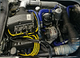
Look at the diagram earlier in this thread. They are usually mounted under one of the coil fixing bolts as close to the connector as possible. The mounting bolt provides the ground.
Dave
London SW
Rover SD1 VDP EFI
MegaSquirt2 V3
EDIS8
Tech Edge 2Y