Desmodromic V8

General Chat About Engine Build

Moderator: phpBB2 - Administrators

Post Reply
manousos
Newbie
Newbie
Posts: 13
Joined: Wed Sep 30, 2009 8:59 am

Desmodromic V8

Post by manousos »

With a Desmodromic (i.e. rid of valve springs) fully Variable (the lift and the duration vary continuously and independently from zero to a maximum) Valve Actuation system (DVVA) like:

Image

the revs and the peak power of a V8 (or of a side-cam engine, in general) increase.

As compared to the conventional engine (left) with the one only valve lift profile (which is used at all revs and loads, from the idling to the peak power), the DVVA provides infinite valve lift profiles, instantly available, like:

Image

resulting in more fuel efficient and green operation.

For more: http://www.pattakon.com/pattakonDesmo.htm

Thanks


unstable load
Top Dog
Top Dog
Posts: 1279
Joined: Mon May 04, 2009 6:53 am

Post by unstable load »

The first mention of a Desmodromic system is in 1896 and an engine was built in 1907 with it. Mercedes Benz's W196 engine used Desmo back in 1954/55 and Ducati has been using it successfully for years, but that system looks too theoretical to be practically efficient in my opinion. It's a proven reality that the fewer linkages and pivots a system has, the more accurately and efficiently it works, particularly if it is going fast and exposed to quite high loads.

Call me a Luddite, if you will.......
Cheers,
John
DaveEFI
Gold Member
Gold Member
Posts: 4603
Joined: Fri Feb 26, 2010 4:27 pm
Location: SW London, UK

Post by DaveEFI »

unstable load wrote:The first mention of a Desmodromic system is in 1896 and an engine was built in 1907 with it. Mercedes Benz's W196 engine used Desmo back in 1954/55 and Ducati has been using it successfully for years, but that system looks too theoretical to be practically efficient in my opinion. It's a proven reality that the fewer linkages and pivots a system has, the more accurately and efficiently it works, particularly if it is going fast and exposed to quite high loads.

Call me a Luddite, if you will.......
The obvious way is to control them electronically, once some form of motor or solenoid that can react fast enough is available.
Dave
London SW
Rover SD1 VDP EFI
MegaSquirt2 V3
EDIS8
Tech Edge 2Y
User avatar
Ian Anderson
Forum Contributor
Forum Contributor
Posts: 2448
Joined: Sun Nov 19, 2006 9:46 pm
Location: Edinburgh

Post by Ian Anderson »

They are available - look at F1 the youe a mis of Desmodronic and Pneumatic valves

IAn
Owner of an "On the Road" GT40 Replica by DAX powered by 3.9Hotwre Efi, worked over by DJ Motors. EFi Working but still does some kangaroo at low revs (Damn the speed limits) In to paint shop 18/03/08.
conrod
Helpful or Confused
Helpful or Confused
Posts: 97
Joined: Sun Dec 20, 2009 6:55 pm
Location: New Zealand

Post by conrod »

DaveEFI wrote:
unstable load wrote:The first mention of a Desmodromic system is in 1896 and an engine was built in 1907 with it. Mercedes Benz's W196 engine used Desmo back in 1954/55 and Ducati has been using it successfully for years, but that system looks too theoretical to be practically efficient in my opinion. It's a proven reality that the fewer linkages and pivots a system has, the more accurately and efficiently it works, particularly if it is going fast and exposed to quite high loads.

Call me a Luddite, if you will.......
The obvious way is to control them electronically, once some form of motor or solenoid that can react fast enough is available.
Mountune developed a system which used specially developed high speed solenoids (10 times faster than the F1 active suspension solenoids, which were the fastest available at the time) to control the opening and closing of the valves in the early 90's, giving infinitely variable lift and duration. As far as I know it was heavily patented and hasn't seen the light of day since.
kiwicar
Forum Contributor
Forum Contributor
Posts: 5461
Joined: Sat Nov 18, 2006 5:00 pm
Location: Milton Keynes

Post by kiwicar »

Looks to me as if someone has found a drawing of a steam engine valve gear system and tacked it onto the drawing of a pushrod engine. Trouble is that all the weight you save associated with valve springs reappears in the linkage, oh and it has to be a push rod engine to get it to fit! Pnumatic valve control systems exist, have been in use in various forms of motorsport for years, so why would you bother with a set up like that?
Best regards
Mike
poppet valves rule!
User avatar
Eliot
Top Dog
Top Dog
Posts: 1765
Joined: Sat Nov 18, 2006 9:46 am
Location: Milton Keynes
Contact:

Post by Eliot »

Ian Anderson wrote:They are available - look at F1 the youe a mis of Desmodronic and Pneumatic valves

IAn
the "Pneumatic" in the F1 valvetrain just replaced the springs, they are still opened with a conventional cam.
Eliot Mansfield
5.7 Dakar 4x4, 4.6 P38 & L322 TDV8
www.mez.co.uk / www.efilive.co.uk
manousos
Newbie
Newbie
Posts: 13
Joined: Wed Sep 30, 2009 8:59 am

Post by manousos »

unstable load wrote:The first mention of a Desmodromic system is in 1896 and an engine was built in 1907 with it. Mercedes Benz's W196 engine used Desmo back in 1954/55 and Ducati has been using it successfully for years, but that system looks too theoretical to be practically efficient in my opinion. It's a proven reality that the fewer linkages and pivots a system has, the more accurately and efficiently it works, particularly if it is going fast and exposed to quite high loads.
Call me a Luddite, if you will.......

When you can achieve the same characteristics by a simpler mechanism, “the simpler the better”.

On the other hand:
The two stroke is simpler, yet the four stroke dominates.
The single cylinder is simpler, yet the cars use only multicylinders.
The V8 is more complicated than the straight four, yet the V8 is better.

As compared to the single valve-lift-profile of the conventional V8 and of the desmodromic systems of Mercedes, Ducati etc mentioned, the BMW valvetronic provides infinite valve lift profiles (allowing the engine to run using valve lift profile closer to the ideal for the instant conditions of operation, achieving better fuel efficiency / greener operation) and this justifies the additional linkages, pivots, rollers etc of the valvetronic.

The pattakon DVVA provides infinite times more valve lift profiles than the valvetronic of BMW.
Think: for each valve lift, the valvetronic has only one available valve duration, while the DVVA has infinite, i.e. it can better approach the ideal valve lift profile.

Your conventional V8 and the old desmodromic engines run, from the idling to the red line, at a single point –like the C- of the Lift-Duration plot below:

Image

the BMW’s valvetronic runs at any point along the LM-VVA curve,

and the pattakon DVVA runs according any point in the FVVA hatched area (for more: http://www.pattakon.com/pattakonFVVA.htm ).

The more variable the valve-lift-profile, the better the engine (Toyota uses their valvematic, Nissan Infinity uses their VVEL, Fiat uses their MultiAir and so on).


The conventional V8 uses valve springs to restore the valves.
The BMW valvetronic, besides the conventional valve springs uses also additional springs to restore the parts of the valvetronic mechanism.
The pattakon DVVA needs no springs, at all, allowing way higher revs.


The DVVA is the evolution / combination of the pattakon VVA rod version
(at http://www.pattakon.com/pattakonRod.htm )
and of the pattakon VVA roller version
(at http://www.pattakon.com/pattakonRoller.htm ),
both made and tested for long on the roads.
Open the video of the four-cylinder 1600cc VVA roller prototype car at http://www.pattakon.com/vvar/OnBoard/A1.MOV

Image

It runs throttle-less at 9000 rpm (with racing valve springs) and asks for more.
The same car idles at 330 rpm stoichiometric (1 liter of fuel per three hours) and has a flat torque curve from below 1000rpm to above 9000rpm.
All these with a zero-cost true-free-flow ITB (a part of the conventional intake plenum):

Image

These are not theoretical (nor their evolution, the DVVA system).


Most VVAs control exclusively the intake valves, either because of cost, or because they cannot control the exhaust valves. The following is a copy from engine-technology-INTERNATIONAL:

. . . Valeo refers to the design (i.e. their electromagnetic VVA) as "half camless". The reason for this is that the forces required to operate the exhaust side are so high, the performance benefits are off set by the increased parasitic losses . . . The spokesman adds: The main benefits are on the inlet side as pumping losses can be reduced. We concluded that if 80% of the benefit is on the inlet side, then this is the best balance. . . . the two concepts together (the electromagnetic "half camless" and a mild hybrid based on StARS+X technology) have been given a dramatic boost by the award of US$108 million (a hundred and eight million US dollars) from the French Industrial Innovation Agency

Unless I am wrong, even with the US$108 millions of the award, there is not one car or motorcycle with electromagnetic valve train on the roads.

The only successful semi-electromagnetic VVA is the electro-hydraulic system of Fiat / Schaeffler-INA (more at http://www.pattakon.com/pattakonHydro.htm )


The pneumatic springs of the Formula1 and motoGP are just pneumatic springs. The engine still operates in a single mode.

This:

Image

DVVA demonstration prototype (twice exhibited at engine-expo Stuttgart Germany) is for DOHC engines.
Yet the side-cam V8 engines with the push-rods have a lot to gain by the DVVA.

Thanks
unstable load
Top Dog
Top Dog
Posts: 1279
Joined: Mon May 04, 2009 6:53 am

Post by unstable load »

When you can achieve the same characteristics by a simpler mechanism, “the simpler the better”.
This being the case, the system utilised by Ducati today is the simplest and by your definition, the best.

All I was saying in my reply was that the more linkages, gears, levers and bits there are in a mechanical system, the more potential fail points there are. Throw in the environment that your average valve gear operates in and you have a recipe for either a seriously overweight and inertia loaded system or a lightweight, failure-prone system.
Cheers,
John
kiwicar
Forum Contributor
Forum Contributor
Posts: 5461
Joined: Sat Nov 18, 2006 5:00 pm
Location: Milton Keynes

Post by kiwicar »

Sorry to say this but it looks a real case of "just because you can doesn't mean you should". It looks like a production nightmare, too many intricate components, a maintenence head ache, and more weight where you don't want it. As said a couple of times earlier, as there are hydraulic/pnumatic valve actuation systems out there (and the opening of the valves on some systems is not controled by a cam but by hydraulic pressure) why bother with a system like that, 40 years ago it might have been worth developing such a system but not now.
Best regards
Mike
poppet valves rule!
manousos
Newbie
Newbie
Posts: 13
Joined: Wed Sep 30, 2009 8:59 am

Post by manousos »

unstable load wrote:
When you can achieve the same characteristics by a simpler mechanism, “the simpler the better”.
This being the case, the system utilised by Ducati today is the simplest and by your definition, the best.
No, this is not the case.
The definition starts with "when you can achieve the same characteristics". Ducati's mechanism cannot.

The desmodromic of Ducati operates in a single mode (in a specific opening-closing motion of the valve -called valve lift profile- defined by the camlobes and the linkage used).
A Ducati Desmo operates from the idling to the red line with the same valve lift profile, say 260 crank degrees duration and 10mm valve lift (like the point C of the Lift-Duration plot).

This unique valve lift profile may be optimized for the peak power at high revs, but then the engine operates not so good at medium/low revs - partial/light loads.
Or this unique valve lift profile may be the optimum for medium revs - half load operation, but then the peak power of the engine is not as high as it could, neither the idling as smooth and as green as it could.


Take now the DVVA for a side cam engine:

Image

If, during operation, the DLC yellow track is rotated counter-clock-wise for a few degrees about the black cross , the valve duration is decreased.
If, also during operation, the pin LC is rotated clock-wise for a few degrees about the black cross, the lift of the valve decreases.
The valve lash remains unchanged.
The acceleration and jerk remain normal.
I.e. you can change, on-the-fly, the characteristics of the valve lift profile in order to be optimized for the instant needs.

It is like having an infinity of camshafts in the "pocket" of the DVVA, and use, each moment, the best for the instant conditions of operation.

And because the valve lift varies from almost zero, a throttle valve is no longer necessary because the intake valves make the throttling. Think of the cost of a decent ITB.


The simpler Ducati Desmo mechanism is not better because it can achieve only a small fraction of what the DVVA mechanism can.


The DVVA idles more smoothly at lower revs at lower consumption, the DVVA provides more flat torque curve, the DVVA can make more power, the DVVA has lower consumption and emissions at all revs-loads, and so on.
This is so because the valve lift profile the DVVA operates can be adjusted / optimized for the instant operational conditions.


One by one the car makers leave the simpler conventional valve train and proceed to the complicated variable valve actuation systems (VVA).

The VVAs used by BMW, Toyota, Nissan, Fiat etc are far more complicated and expensive and faulty than the conventional single mode valve train. However, their additional cost / complication / faults etc are justified by the improvement of the operation of the engine (mileage, emissions, peak power, response, smoothness, driver friendly operation etc).


Like: the two stroke is simpler, yet the four stroke dominates.


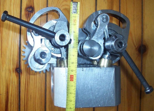
Below is an Over Head version of the DVVA, with a single "camshaft".

ImageImageImage


Left: the two "Lost Motion Control Shafts" (each having a track or groove or slot -magenta- along which the yoke roller and its pin roll, being in simultaneous abutment to both sides/surfaces/walls of the track) are at angles providing short duration and negative overlap.

Middle: the Lost Motion Control Shafts are at angles providing long duration, while the Constant Duration Control Shafts (they displace the pin of the big end of the red rods) are at angles providing medium valve lift. Here the angular overlap is long while the actual overlap (valve-time area) is medium.

Right: the Lost Motion Control Shafts are at angles providing long duration, while the Constant Duration Control Shafts are at angles providing high valve lift. The angular overlap is long. The actual overlap (valve-time area) is extreme.

The external ring (yoke) of the roller rolls along the upper surface of the track and has nothing to do with the lower surface of the track; similarly the pin of the roller rolls along the lower surface of the track and has nothing to do with the upper surface of the track. This way there is no "sliding" friction in the mechanism. The proper dimensioning of the track defines the preloading of the roller / track assembly.

Note: the only heavy parts are the tracks; and the tracks move slowly, and only when a different valve duration is necessary. All the rest quick moving parts are lightweight and are rid of bending loads.

So,
is the Ducati single-mode desmo simpler, or lighter, or more compact, or capable for higher revs, or with less friction than the above infinite-mode DVVA?

Thanks
User avatar
ChrisJC
Top Dog
Top Dog
Posts: 5077
Joined: Mon Nov 20, 2006 1:13 pm
Location: Northants / Cambs
Contact:

Post by ChrisJC »

Very interesting stuff I must say.

Chris.
--
Series IIA 4.6 V8
R/R P38 4.6 V8
R/R L405 4.4 SDV8
Post Reply

Return to “Engines Area”