
V8 Pulley sizes and identification
Moderator: phpBB2 - Administrators
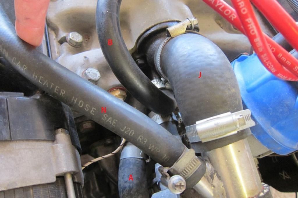
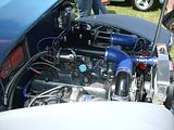
I've taken a closer look at my engine today and I could do with some further clarification. I'd like to understand my cooling system properly and I keep reading conflicting information on the web, particularly regarding the Offenhauser ports on the inlet manfold. I've taken a fresh set of pictures and labelled them all.
So.... as I understand it. (ignore lettering from previous posts)
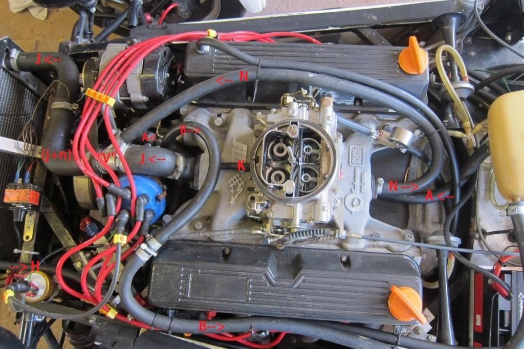
(A) goes from the header to the water pump intake - a pipe sticking out of the top of the water pump main entry pipe. This is so the pump can drag water from the header when needed or there is a pressure imbalance as water is put in the header via other pipes. Pipe (A) passes under the offy manifold.
(B) comes from a small pipe just below the main inlet manifold outlet (J) and goes back to the header tank near the top.
(J) Goes to the rad top and is hot water from the engine.
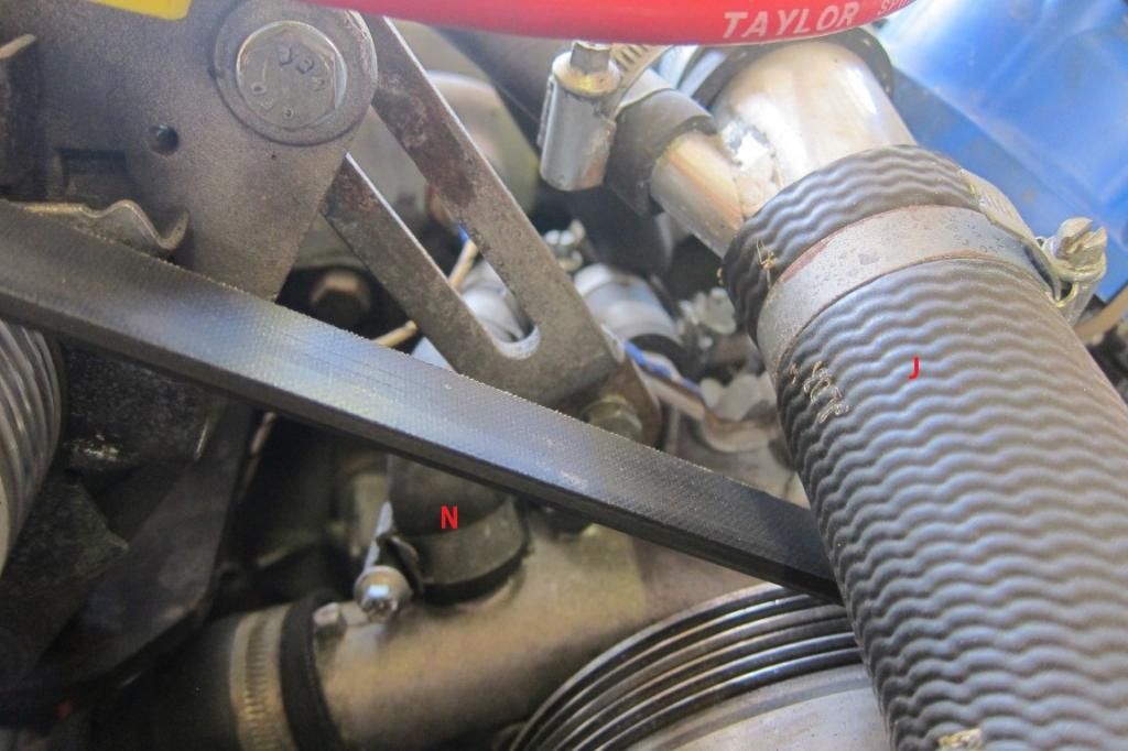
(N) comes out of the other side of the offy and is more hot water that has passed through the head and the inlet manifold. This joins (J) with a "V" anmd heads off to the top of the rad.
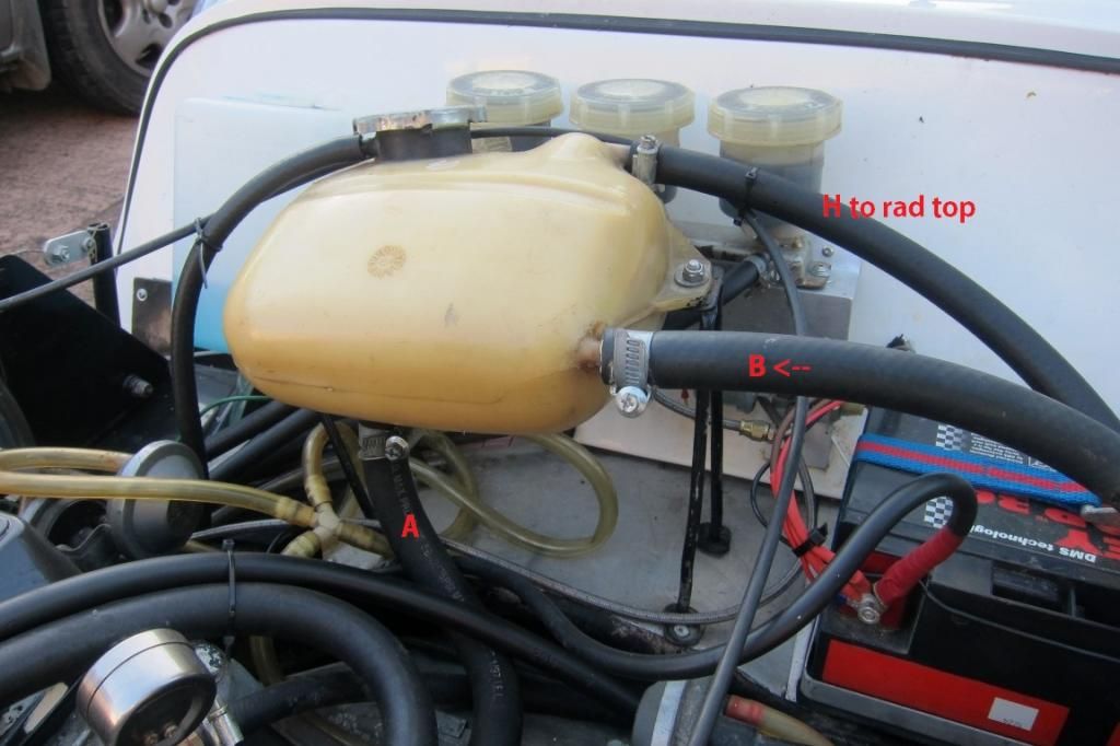
(H) is the bleed pipe from the top of the rad that goes to the very highest point of the header tank.
(K) is a vacuum pipe not needed and blanked off.
I don't now the internals of the offy, and crucually, I dont' know if it's all one water reservoir inside, with J, B and N all being linked, Or, perhaps the water from the engine just comes out of J to the rad , and then B and N are linked and entirely seperate from J - as a pass through for a heater (as I've seen suggested elsewhere)
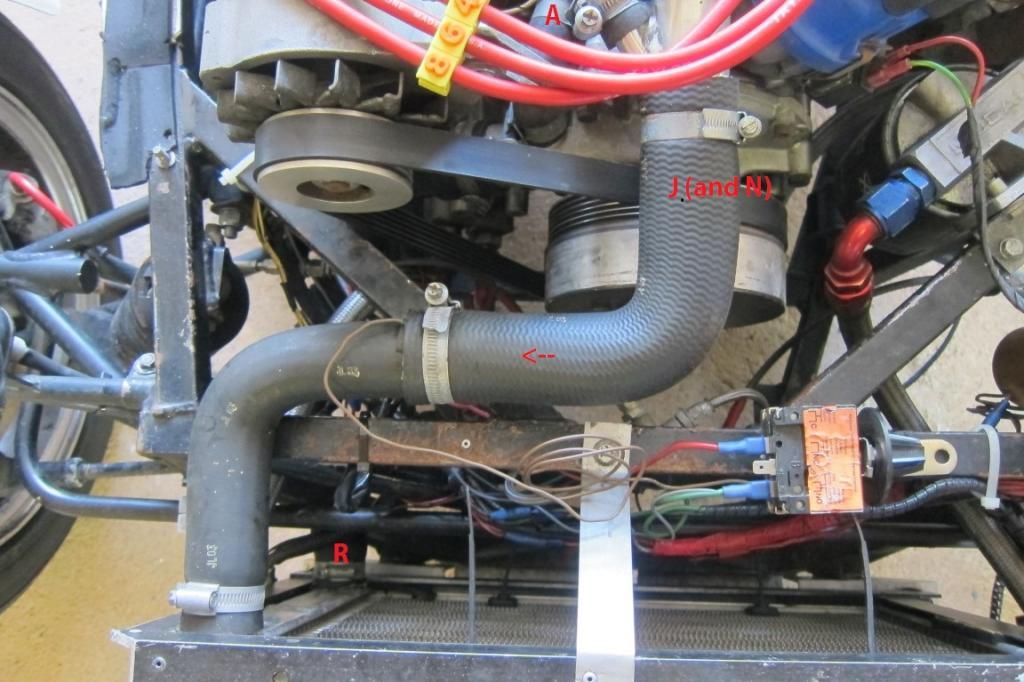
Above - that's (A) coming from the header tank into the top of the pump.
G is blanked with a bolt - is this another "input" into the water pump? I think I've seen offy heads where the output (B) i splumbed stright into this.
Some more angles:
If I've got any of the water directions wrong I'd be keen to know. I'm a little confused about the offy inlet manifold - I just don't know for sure how it's plumbed internally, and if I install a stat, where the bypass is going to go, as I'd assumed the small pipe (B) was the bypass, but googling has suggested perhaps it's not?
Also, If I've got the logic and flow right , then B really should go to the blanked off spare "input" into the water pump, (G) - as it's currently running all the way to the header tank, to end up making the same journey back into the water pump!
So.... as I understand it. (ignore lettering from previous posts)
(A) goes from the header to the water pump intake - a pipe sticking out of the top of the water pump main entry pipe. This is so the pump can drag water from the header when needed or there is a pressure imbalance as water is put in the header via other pipes. Pipe (A) passes under the offy manifold.
(B) comes from a small pipe just below the main inlet manifold outlet (J) and goes back to the header tank near the top.
(J) Goes to the rad top and is hot water from the engine.
(N) comes out of the other side of the offy and is more hot water that has passed through the head and the inlet manifold. This joins (J) with a "V" anmd heads off to the top of the rad.
(H) is the bleed pipe from the top of the rad that goes to the very highest point of the header tank.
(K) is a vacuum pipe not needed and blanked off.
I don't now the internals of the offy, and crucually, I dont' know if it's all one water reservoir inside, with J, B and N all being linked, Or, perhaps the water from the engine just comes out of J to the rad , and then B and N are linked and entirely seperate from J - as a pass through for a heater (as I've seen suggested elsewhere)
Above - that's (A) coming from the header tank into the top of the pump.
G is blanked with a bolt - is this another "input" into the water pump? I think I've seen offy heads where the output (B) i splumbed stright into this.
Some more angles:
If I've got any of the water directions wrong I'd be keen to know. I'm a little confused about the offy inlet manifold - I just don't know for sure how it's plumbed internally, and if I install a stat, where the bypass is going to go, as I'd assumed the small pipe (B) was the bypass, but googling has suggested perhaps it's not?
Also, If I've got the logic and flow right , then B really should go to the blanked off spare "input" into the water pump, (G) - as it's currently running all the way to the header tank, to end up making the same journey back into the water pump!
Sorry to come in late on this one.
I believe the problem is pipe A. It is causing low pressure in the header tank and therefore effectively sucking hot coolant through pipe B and the small pipe connected to the top of the rad. It is therefore pulling coolant away from the rad in addition to the normal bad effects of when coolant is permitted to bypass the rad.
You only need one 15mm pipe connected to the system from the header tank to allow filling and the small pipe is then just a bleed to allow air to purge from the top of the rad.
Try a test by clamping pipe A. With no stat fitted flow in B will be small/zero as flow through the header tank will only see the pressure difference in the length of the top hose.
Regards Denis
1950 A40 Devon Hotrod with 5.0 twin turbo RV8.
EDIS8 wasted spark, Holley Injection.
Been as far as the Moon and back in 57 years of driving. Same Car, 5 engine upgrades !!!
EDIS8 wasted spark, Holley Injection.
Been as far as the Moon and back in 57 years of driving. Same Car, 5 engine upgrades !!!

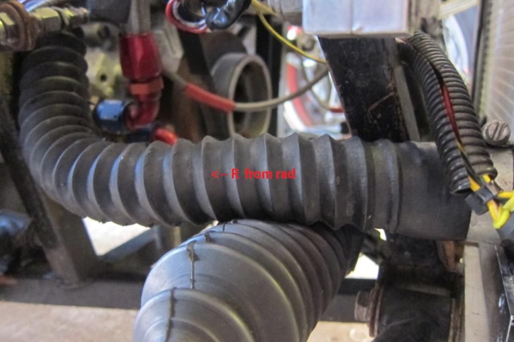
Thanks. I see your logic, though I thought Pipe A was a fairly standard connection for the header feed - or should it go further down and "Tee" into the lower rad pipe as opposed to going straight into the pump? i.e. at present it is actively being "sucked" by the pump?, where as if I "Tee" it into the lower rad pipe (R) somewhere before the pump then it'll top the system up but won't be drawn on much?
I'll try clamping it tomorrow.
I'll try clamping it tomorrow.

G is an input to the water pump. So yes, normally B would go straight into here. That would be the thermostat bypass.
N would normally go via the heater matrix into A on the pump.
So the two differences between your setup and a standard one are:
B->A is the thermostat bypass circuit, which you have going via the header tank rather than a very short piece of pipe.
N is feeding into the top hose rather than the bottom hose. This is the most worrying one I think - I would try clamping that one as it's not doing anything.
Chris.
--
Series IIA 4.6 V8
R/R P38 4.6 V8
R/R L405 4.4 SDV8
Series IIA 4.6 V8
R/R P38 4.6 V8
R/R L405 4.4 SDV8
Cool. I'm slowly building up a picture here.
Funny you should say that, I've read on the Locost forum that output "N" should just be blanked off.
http://www.locostbuilders.co.uk/viewthr ... tid=165352
I'm curious why someone went to so much trouble to install "N" into the "V" joint with "J" - it's there specifically just for "N"
Funny you should say that, I've read on the Locost forum that output "N" should just be blanked off.
http://www.locostbuilders.co.uk/viewthr ... tid=165352
I'm curious why someone went to so much trouble to install "N" into the "V" joint with "J" - it's there specifically just for "N"
OK , so I did some testing yesterday. With the body work off.
She climbs to 93 ish and then very very clowly climbs to 100 (at tickover) Fan comes in around mid 80's.
I bought an infra red thermometer.
Water pipe going into rad: 93
Water pipe exiting rad: 72
I did vavious tests and seem to be consistently getting around a 20 degree drop.
On the rad itself I get 90 at the top left (input), 70 on the right corner, 73 bottom right, 68 bottom left (exit). This is all areas not covered by the fan.
I clamped A which made no noticeable difference at all (when wamed up to mid 90's)
I clamped B which was the same - no difference.
I even clamped N which unsurprisingly made no difference. I'm inclined to blank that one off.
So, my plan so far, just to tidy things up if nothing else:
Swap the header tank for a nice Ally one I have.
Remove pipe B and plug B into G with an offset pip - this seems to be something everyone does - B to G.
I may insert an extra air return / auto bleed pipe (like existing H) higher up the system as the top of the rad where it goes is far from the highest point of the cooling system. Tee'ing out of N might be best, I might even blank off N and Tee out of it with a small pipe.
Sound logical?
Here is what I've done.
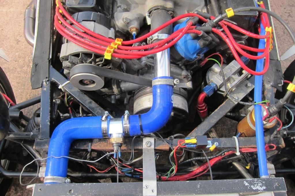
I've removed the pipe from the rear of the manifold, and plumbed the bypass direct into the pump. I've also installed an inline fan temp switch, though I've bought too high a temp one - 95/86 , so I've odere another (fiat panda!) which is 92/87. If that's still too high then I'll get a sub-90 one, but they don't go off until under 80, which will never happen!
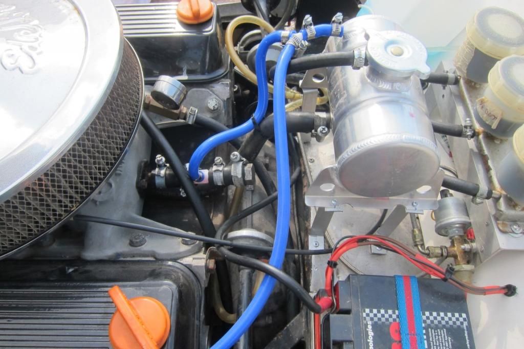
I've also installed my alloy tank, and where I removed the pipe form the back of the manifold, I've instead reduced to to 6mm and joined it with the rad bleed pipe where they meet the tank as the rear top of the manifold is the highest part of the plumbing so I'm hoping it will enhance the auto bleeding.
I've also installed a 76 degree stat which is working as it should.
I've removed the pipe from the rear of the manifold, and plumbed the bypass direct into the pump. I've also installed an inline fan temp switch, though I've bought too high a temp one - 95/86 , so I've odere another (fiat panda!) which is 92/87. If that's still too high then I'll get a sub-90 one, but they don't go off until under 80, which will never happen!
I've also installed my alloy tank, and where I removed the pipe form the back of the manifold, I've instead reduced to to 6mm and joined it with the rad bleed pipe where they meet the tank as the rear top of the manifold is the highest part of the plumbing so I'm hoping it will enhance the auto bleeding.
I've also installed a 76 degree stat which is working as it should.
