
Hi I am trying to learn as much as I can about the 14CUX system as used on the Rover 3.9 and bigger engines in the TVR as i am looking at using this in another vehicle.
First, is when the vehicle just has an old style speedo drive what is done to send a speed signal to the 14CUX ECU?
Second, for engine speed what specifically is the 14CUX ECU taking - just a tacho signal or the low tension signal to the coil. If EDIS 8/Megajolt was fitted it is the SAW signal going back to EDIS 8 that determines ignition firing advance - will the 14 CUX ECU also use this SAW signal to determine when to fire the injectors? For ignition, EDIS recognises the missing trigger wheel tooth to determine where to start the firing sequence, how does 14CUX determine when to start the batch firing sequence of the injectors?
Third - Tune resistors. I have an early ECU so will have a tune resistor - Red 180 ohms as per this list.
Available resistors were as follows
White 3900 Ohms USA and European vehicles with catalytic converters
Green 470 Ohms UK and European vehicles without catalytic converters
Yellow 910 Ohms Saudi vehicles (without catalytic converters.)
Red 180 Ohms Australia and "the rest of the world.
Does anyone know what the tuning impact is in changing the tune resisitor - for example from Red to yellow or green?
Thanks
Garry
Learning about the 3.9 14CUX ECU
Moderator: phpBB2 - Administrators
Re: Learning about the 3.9 14CUX ECU
All IIRC.
SAW is a signal generated by MegaSquirt, etc, that EDIS uses to alter the ignition timing. Don't think the 14CU generates anything similar. If you want to use EDIS with the 14CU (other than at fixed ignition setting) you'll need to use an MS or Megajolt too.
The Lucas system is batch fire, each bank fires alternately and fires twice per engine cycle. It is not timed relative to TDC. For timed injection - usually called sequential - you'd need a cam position sensor too, as the crank trigger can only give crank TDC, not which cylinder is at TDC.
PIP from EDIS is merely an engine speed signal (tach) It doesn't contain the missing pulse from the 36-1 trigger wheel, so no engine position information. EDIS uses the 36-1 wheel to determine firing point within its own ECU, but has no need to pass on that information.
If your gearbox has a mechanical speedo drive, or non at all, it's possible to add an electronic one using the propshaft. For example the bolts on a UJ with a sensor counting them. Or add a trigger wheel. Which would have to be made. Think you might also find a pulse generator which can be inserted in the speedo drive - but dunno if there is one which replicates the pulses from the LT77, etc.
Not sure what changing the tune resistors actually does.
Hope most of that is correct. I've not really had anything to do with the hotwire.
Dave
London SW
Rover SD1 VDP EFI
MegaSquirt2 V3
EDIS8
Tech Edge 2Y
London SW
Rover SD1 VDP EFI
MegaSquirt2 V3
EDIS8
Tech Edge 2Y
Re: Learning about the 3.9 14CUX ECU
I am happy with the ignition side of things however for the Lucas 14CUX system to batch fire twice per engine cycle it still needs some sort of input to determine where the crankshaft is - so what I am looking for is how the 14CUX system gets this information - my assumption is that on its normal dizzy system it is from the low tension side of the coil, which is similar to the SAW signal from MS or MJ.DaveEFI wrote: ↑Sun Apr 21, 2019 9:08 am
The Lucas system is batch fire, each bank fires alternately and fires twice per engine cycle. It is not timed relative to TDC. For timed injection - usually called sequential - you'd need a cam position sensor too, as the crank trigger can only give crank TDC, not which cylinder is at TDC.
Not looking at timed injection - just the way that 14CUX does it.
Cheers
garry
Re: Learning about the 3.9 14CUX ECU
I'd guess the ECU may fire the injectors at an interval determined by the tach pulses. But if this was optimal for one cylinder, it would be wrong for all the others. Since you have four injectors firing at once. And twice per cycle.
Fully timed injection gives very little improvement in practice - mainly towards the lower rev range and emissions.
You can alter the injection grouping to follow the firing order more closely. Jury is out as to whether you'd notice it. Possibly a better idle.
Fully timed injection gives very little improvement in practice - mainly towards the lower rev range and emissions.
You can alter the injection grouping to follow the firing order more closely. Jury is out as to whether you'd notice it. Possibly a better idle.
Dave
London SW
Rover SD1 VDP EFI
MegaSquirt2 V3
EDIS8
Tech Edge 2Y
London SW
Rover SD1 VDP EFI
MegaSquirt2 V3
EDIS8
Tech Edge 2Y
Re: Learning about the 3.9 14CUX ECU
14CUX gets signal from the LT side of the coil for engine speed, won't even start the fuel pump u til it sees this.
Road speed signal is used to switch from the elevated "moving idle" to regular idle at a out 3MPH, also used in some 4WD installations to limit top speed due to tyre speed rating.
I installed a pulse generator in the speedo drive cable when I did mine, now I can see the signal in Rover Gauge I realise it is slightly different to real speed, not a problem as I dont have a speed limit on my chip. I believe TVR had a pulse generator which tured on when car was moving but at a constant rate so it only controls moving idle.
I'd suggest looking into Rover Gauge if you didn't already.
Re: Learning about the 3.9 14CUX ECU
Thanks for those responses. I will look into the speed sendor aspect - I have an old cruise control kit lying around which uses magnets strapped to the drive shaft with a sensor - that should work as the 14CUX just needs to know if the vehicle is moving or not
So to be specific, with ignition being controlled by EDIS 8 and Megajolt what connector on the EDIS connect will provide ignition timing to the 14CUX ECU - my logic says the SAW signal from Megajolt back to EDIS as this best mimics the function of B+ on the low tension side of the coil. The other option is simply the +ive wire that goes to the coil packs as its current is broken each time a firing pulse is send to the coils and allows the current to flow to earth as the coil fires - like a traditional coil.
Cheers
Garry
Re: Learning about the 3.9 14CUX ECU
If you have an MJ controlling EDIS both PIP and SAW are already in use. Taking an extra feed from one of those to drive the hotwire might prove tricky - ground loops and so on. And I don't think the SAW signal is suitable anyway.
Have a pal with EDIS and MJ on his SD1, which has the flapper injection. That too uses the coil negative to trigger the injection.
Since there are four coils rather than one, you can't take a signal from one of those coil negatives as it would show the wrong RPM. The same problem as driving a rev counter from EDIS.
The usual way round this is to build or buy a diode network adaptor unit to link all four coil negatives together to provide a tach signal with the same number of pulses as a single coil. You'll find details in the MJ (or MS) instructions.
On EDIS 8, it's also possible to use IDM (pin2). That can be used to drive a rev counter, so is similar to PIP. The fly in the ointment is the pulse from the coil negative is large - about 60v peak. Signals exchanged between ECUs are much smaller.
Dave
London SW
Rover SD1 VDP EFI
MegaSquirt2 V3
EDIS8
Tech Edge 2Y
London SW
Rover SD1 VDP EFI
MegaSquirt2 V3
EDIS8
Tech Edge 2Y
Re: Learning about the 3.9 14CUX ECU
Thanks for those thoughts - needs further investigation.
Surely on Brit UK V8 forum, someone has a 14CUX injected V8 with a Megajolt/EDIS ignition system so has actual answers. Here is hoping but keep thoughts on possible issues coming.
Cheers
Garry
Surely on Brit UK V8 forum, someone has a 14CUX injected V8 with a Megajolt/EDIS ignition system so has actual answers. Here is hoping but keep thoughts on possible issues coming.
Cheers
Garry
Re: Learning about the 3.9 14CUX ECU
Both the hotwire and flapper are triggered in the same way - from the coil negative. On the flapper there is an external 6K8 series resistor to limit the current to the ECU input. Think the hotwire has this resistor too, but not sure of the value.
Dave
London SW
Rover SD1 VDP EFI
MegaSquirt2 V3
EDIS8
Tech Edge 2Y
London SW
Rover SD1 VDP EFI
MegaSquirt2 V3
EDIS8
Tech Edge 2Y
Re: Learning about the 3.9 14CUX ECU
Thinking further on all the responses - how does this sound.
In the standard setup the engine ECU gets its ignition pulse from the LT side of the coil - so it gets 8 pulses per rotation of the dizzy rotor (or 8 pulses every 2 rotations of the crankshaft - each of the 8 pistons only fires once every 2 crank rotations) - it doesn't know the order or anything like that other than it gets 8 pulses.
It is also from this same source that the dash tacho gets its signal - 8 pulses per 2 rotations of the crank.
For a tacho to work off EDIS it requires a module that essentially captures each of the trigger signals to the coil packs and sends these to the tacho - (wiring diagram below) - now while the coil pack is wasted spark so two spark plugs are fired at once - the same number of 8 pulses per 2 rotations of the crank are sent to the coil packs.
To me then - if I send this tacho signal to the ECU it should be no different than the ECU taking the 12v B+ signal from a dizzy and coil.
I have this module connected to my EDIS 8 and it drives the old tacho I have fine - stable and accurate.
Thoughts??
Garry
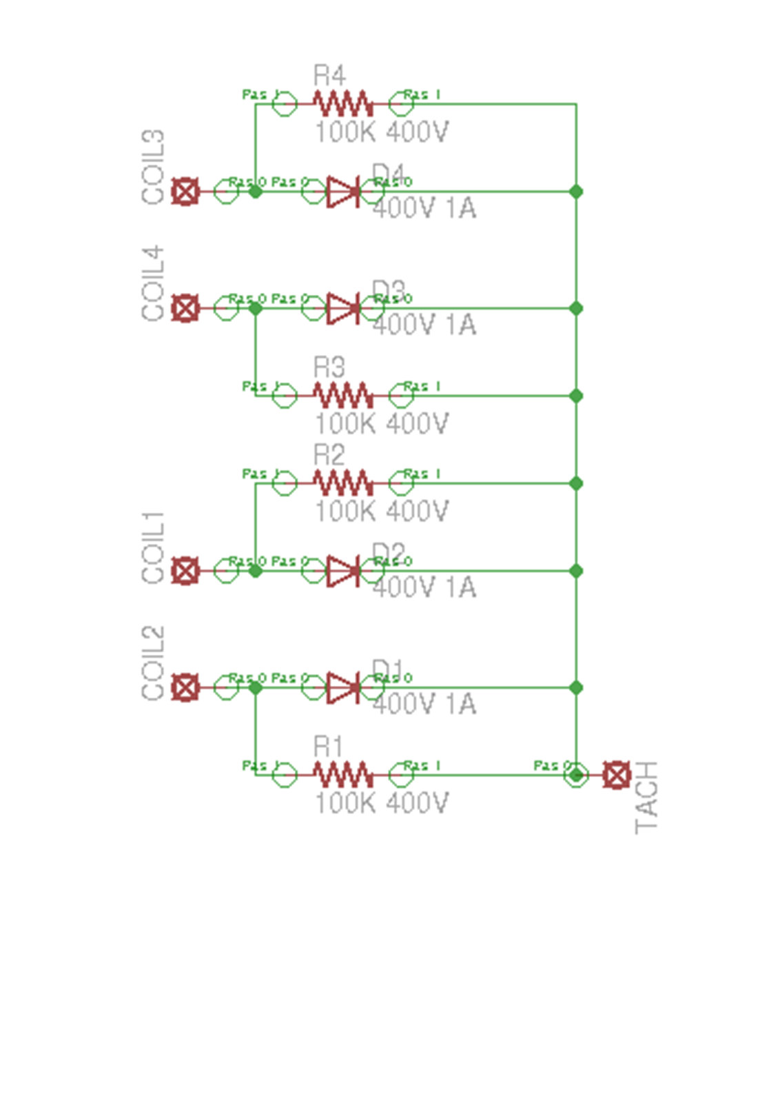 Tach_adapter_sch
In the standard setup the engine ECU gets its ignition pulse from the LT side of the coil - so it gets 8 pulses per rotation of the dizzy rotor (or 8 pulses every 2 rotations of the crankshaft - each of the 8 pistons only fires once every 2 crank rotations) - it doesn't know the order or anything like that other than it gets 8 pulses.
It is also from this same source that the dash tacho gets its signal - 8 pulses per 2 rotations of the crank.
For a tacho to work off EDIS it requires a module that essentially captures each of the trigger signals to the coil packs and sends these to the tacho - (wiring diagram below) - now while the coil pack is wasted spark so two spark plugs are fired at once - the same number of 8 pulses per 2 rotations of the crank are sent to the coil packs.
To me then - if I send this tacho signal to the ECU it should be no different than the ECU taking the 12v B+ signal from a dizzy and coil.
I have this module connected to my EDIS 8 and it drives the old tacho I have fine - stable and accurate.
Thoughts??
Garry
Tach_adapter_schRe: Learning about the 3.9 14CUX ECU
That is the diode unit adaptor I referred to earlier. Several varieties to the circuit, though. Not sure you need the resistors at all. Where did you find that circuit?
Dave
London SW
Rover SD1 VDP EFI
MegaSquirt2 V3
EDIS8
Tech Edge 2Y
London SW
Rover SD1 VDP EFI
MegaSquirt2 V3
EDIS8
Tech Edge 2Y
Re: Learning about the 3.9 14CUX ECU
I cannot recall where I found it but it was from a commercial site - they were selling made up modules but also had the wiring diagram for those who wanted to make their own - as i said it works well and was simple to make.
Re: Learning about the 3.9 14CUX ECU
Ah - thanks for that. Rev counters can be a bit tricky to get just right, depending on model.
Although the pulse count is the same for both the rev counter and triggering the ECU, both MJ and MS can provided a 'proper' 5v pulse stream to drive that ECU, which may be easier to use. To connect that to either the flapper or hotwire, you'd remove the series resistor.
Although the pulse count is the same for both the rev counter and triggering the ECU, both MJ and MS can provided a 'proper' 5v pulse stream to drive that ECU, which may be easier to use. To connect that to either the flapper or hotwire, you'd remove the series resistor.
Dave
London SW
Rover SD1 VDP EFI
MegaSquirt2 V3
EDIS8
Tech Edge 2Y
London SW
Rover SD1 VDP EFI
MegaSquirt2 V3
EDIS8
Tech Edge 2Y
Re: Learning about the 3.9 14CUX ECU
Back to speed input to the 14CUX (Hotwire) ECU.
I am looking at this to provide speed input to a 14CUX (Hotwire) ECU in my FC101. A friend also has a FC101 with 14CUX system and he does not have any speed input to his ECU and the vehicle runs and idles fine.
So is speed input important to the 14CUX Hotwire ECU?
Thanks
Garry
I am looking at this to provide speed input to a 14CUX (Hotwire) ECU in my FC101. A friend also has a FC101 with 14CUX system and he does not have any speed input to his ECU and the vehicle runs and idles fine.
So is speed input important to the 14CUX Hotwire ECU?
Thanks
Garry
Re: Learning about the 3.9 14CUX ECU
You are not getting the answers because people dont take the path you are considering.
You either stick to 14cux and dizzy - which as you are discovering the ECU just takes an input from the LT side of the coil. It doesn't perform any timing relevant to when the valves are open or close (FWIW Megasquirt does the same thing even when using a trigger wheel) - all known as batch mode.
If you are going to replace the dizzy (recommended) then simply replace 14CUX at the same time rather than trying to make the two essentially incompatible (and inferior) systems work together.
If you want to take things step by step, first replace the 14cux with megasquirt triggered off a wheel(recommended) OR the neg side of the coil. Once you have fueling stable and you are happy with it, replace the ignition with coilpacks/edis (which will need a wheel). This is essentially the path i took, as it was easy to roll back if i had a problem.
