
Hi John
I did look at placing the filters behind the headlights but that would have meant getting more bends and it would have not been that easy to get the 3" tubes in there.
Also it would disrupt the airflow so placement has been determined by space as well as for airflow.
Thanks for you kind comments.
More progress to come soon.
cheers
P
Monkey business
Moderator: phpBB2 - Administrators
Hi Paul, Is that the Plug your creating. So once your happy with that you make a mould and then that's used to make the filter.
Is it going to be a two part mould and where will the parting lines be. Dont answer that as its like telling someone the next chapter in a book and will spoil the next installment
regards
Reg
Is it going to be a two part mould and where will the parting lines be. Dont answer that as its like telling someone the next chapter in a book and will spoil the next installment
regards
Reg
Hiya mate
Nice to hear from you we have'nt spoken since our impromptu meeting last year and Im still waiting for the photos you said you would send!!!
You are correct in assuming that this is the plug and yes it has to be a two part mould as there is no way that a finished unit would be possible to gel and glass if a one piece mould and also it would never release.
I have a cunning plan when it comes to fixing the two halves together but all will be revealed as this long time coming induction system comes together (he typed hopefully )
)
I have never attempted to cobble something like this together before so as usual I'm just making it up as I go along.
Right gotta get out there now coz I got the whole evening on it YIPPEE
P
Nice to hear from you we have'nt spoken since our impromptu meeting last year and Im still waiting for the photos you said you would send!!!
You are correct in assuming that this is the plug and yes it has to be a two part mould as there is no way that a finished unit would be possible to gel and glass if a one piece mould and also it would never release.
I have a cunning plan when it comes to fixing the two halves together but all will be revealed as this long time coming induction system comes together (he typed hopefully
I have never attempted to cobble something like this together before so as usual I'm just making it up as I go along.
Right gotta get out there now coz I got the whole evening on it YIPPEE
P
Greetings from Gelmonkey Towers.
Well been out and done a bit more tonight and would have liked to have got a bit more done but it is not that warm in the garage and the gel is taking a while to cure so thought it would be best to leave it overnight and continue gelling tomorrow.
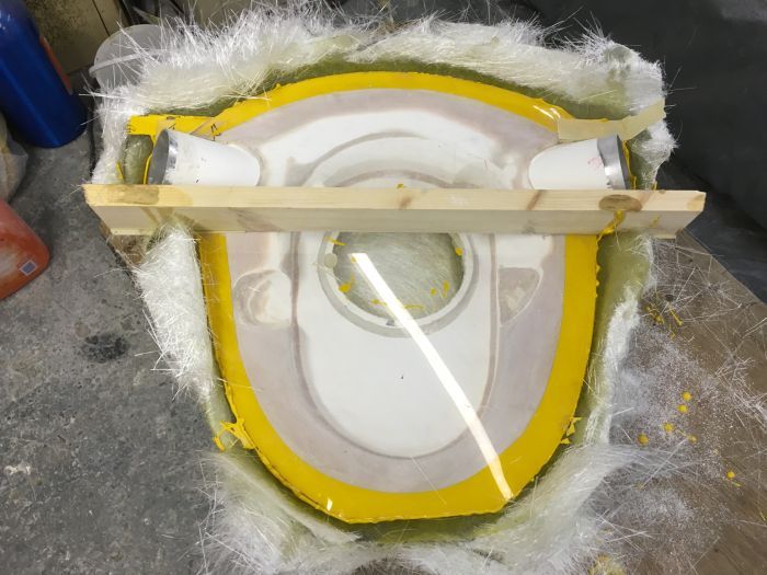
So in the meantime this is what I have done this evening.
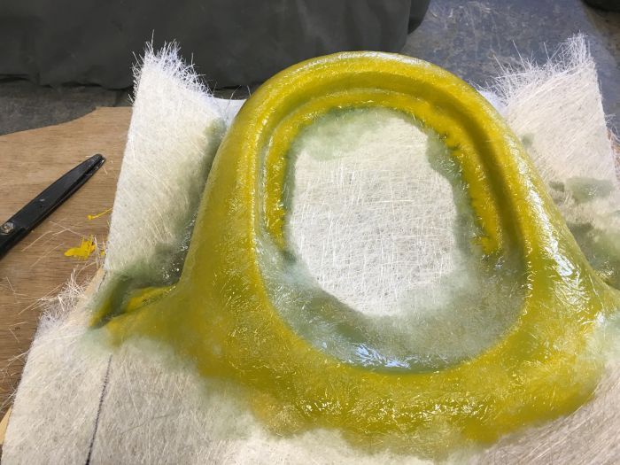
After getting everything straight yesterday evening it was now time to cove in the ends of the tubes with Plasticene
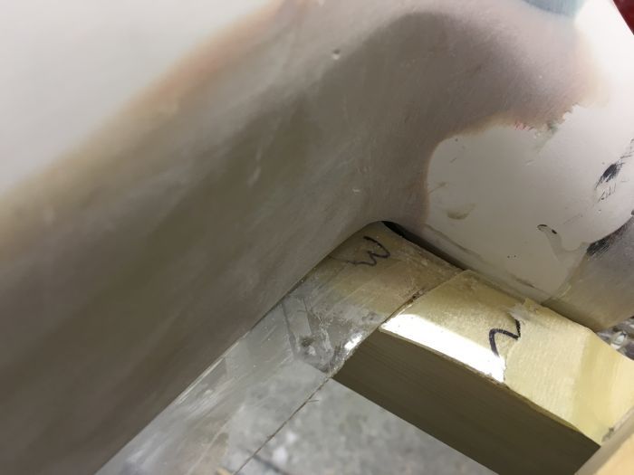
With that done attention then had to turn to the very tight radii that was mentioned yesterday (I think) and how to stop the laminates when applied from lifting off such tight corners.
Also at the bottom of the upper section where the top filter will sit there is a small 'land ' that the glass will have to sit on and not come away from the corners as the glass cures.
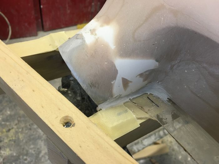
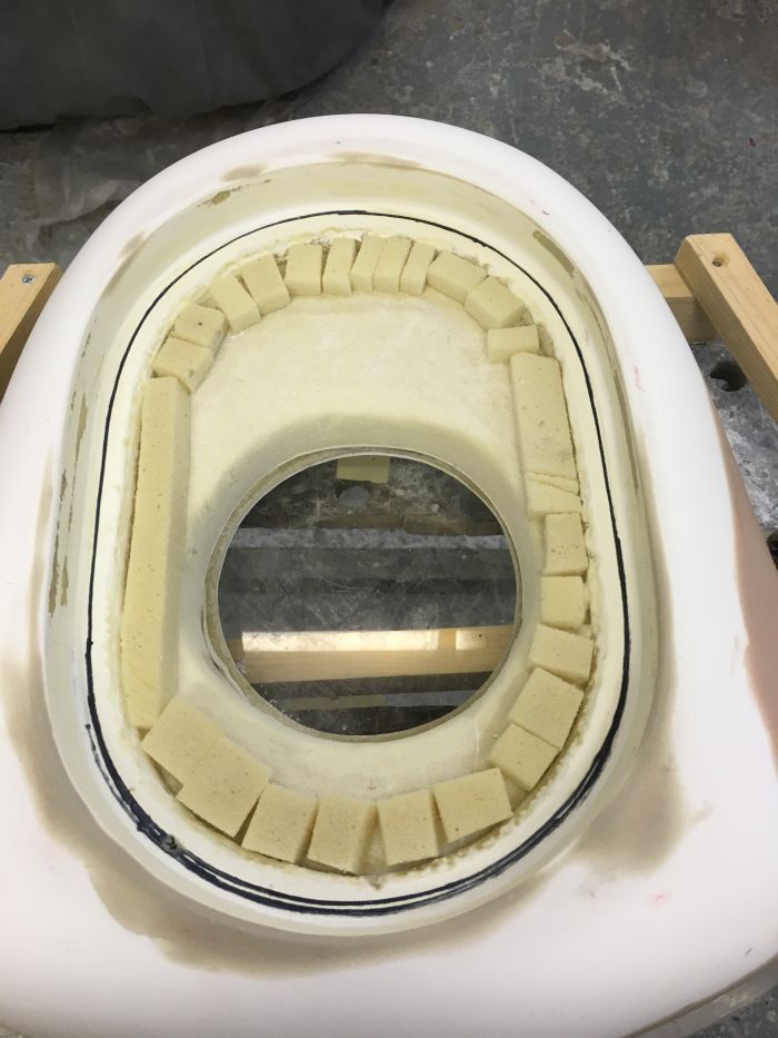
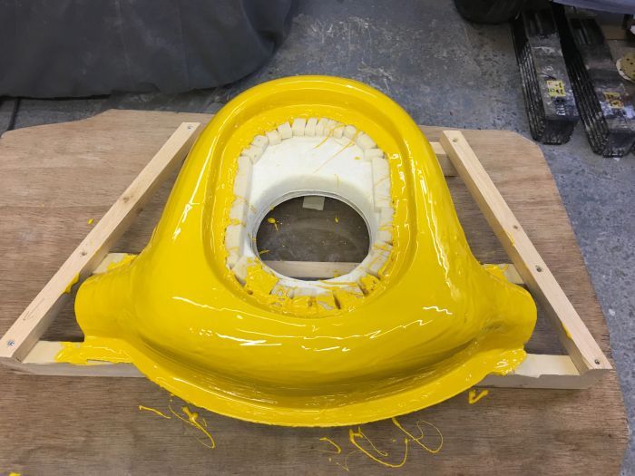
As you can see from the pics the black line denotes where the actual filter sits but I have to take the glass out further than this to keep and equal thickness .
To get around this problem small blocks of foam were cut and just sat in place.
When the gel has been applied that will hold the blocks in place and as they are just sacrificial it does not matter what they look like as long as they do the job required.
To solve the problem of the tight corners plenty of gel is applied which then bulks up the edges and allows the laminates when applied to flow over the curves rather that being forced in and without question the glass would lift away and cause air voids which we do not want.
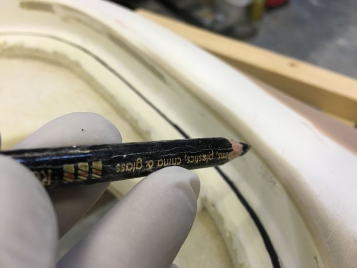
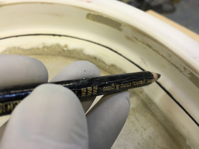
The picture above shows pretty much a right angle so that the filter itself sits square within the housing and would be impossible to glass without the aid of plenty of gel.
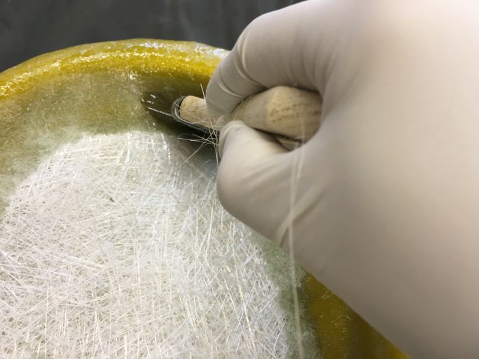
So after waxing the whole thing 8 times it was out with the clear gel and some yellow pigment paste and mix them together.
It is recommended that between 2 and 5% of pigment is used in clear gel but over the years i have found that you can use up to 10 %without any worries so thats roughly what was done here.
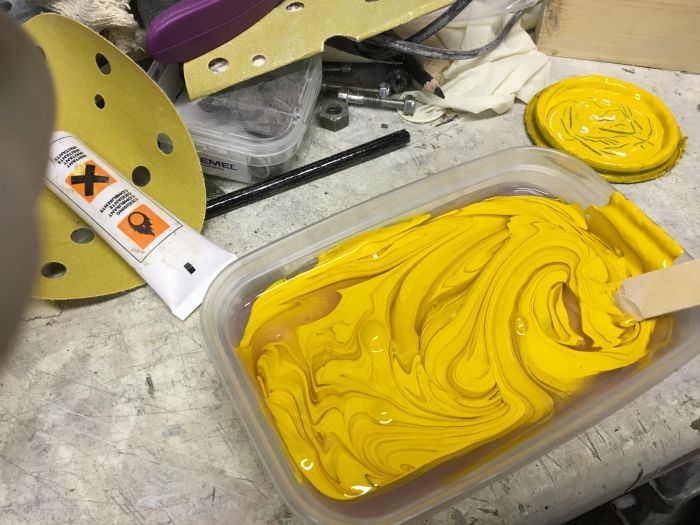
Yellow is a great pigment for mould making because it is such a stark colour against what the final unit colour will be and simple to see the parting lines.
Obviously if you wanted your final unit to be yellow then you would use a different but equally as stark pigment.
After a good mix together and a slug of catalyst along with another good mix it was time to finally get the gelling underway which was done using a 1" brush.
Bung it on and then smooth out so it will more or less level itself out on the top and nit be too heavy on the sides.
Allow to cure and apply 2 more coats which will be done tomorrow during the day.
Its good to be getting on with the real stuff now as whilst the plug making is enjoyable for me there is nothing quite like doing the proper part of the job.
On a final note for tonight I am often asked why do you need to make a pattern?
The answer is simple in as much as you have to make a positive to make a negative to make a positive.
Basically its just pattern making
cheers
P
Well been out and done a bit more tonight and would have liked to have got a bit more done but it is not that warm in the garage and the gel is taking a while to cure so thought it would be best to leave it overnight and continue gelling tomorrow.
So in the meantime this is what I have done this evening.
After getting everything straight yesterday evening it was now time to cove in the ends of the tubes with Plasticene


With that done attention then had to turn to the very tight radii that was mentioned yesterday (I think) and how to stop the laminates when applied from lifting off such tight corners.
Also at the bottom of the upper section where the top filter will sit there is a small 'land ' that the glass will have to sit on and not come away from the corners as the glass cures.
As you can see from the pics the black line denotes where the actual filter sits but I have to take the glass out further than this to keep and equal thickness .
To get around this problem small blocks of foam were cut and just sat in place.
When the gel has been applied that will hold the blocks in place and as they are just sacrificial it does not matter what they look like as long as they do the job required.

To solve the problem of the tight corners plenty of gel is applied which then bulks up the edges and allows the laminates when applied to flow over the curves rather that being forced in and without question the glass would lift away and cause air voids which we do not want.


The picture above shows pretty much a right angle so that the filter itself sits square within the housing and would be impossible to glass without the aid of plenty of gel.
So after waxing the whole thing 8 times it was out with the clear gel and some yellow pigment paste and mix them together.
It is recommended that between 2 and 5% of pigment is used in clear gel but over the years i have found that you can use up to 10 %without any worries so thats roughly what was done here.


Yellow is a great pigment for mould making because it is such a stark colour against what the final unit colour will be and simple to see the parting lines.
Obviously if you wanted your final unit to be yellow then you would use a different but equally as stark pigment.
After a good mix together and a slug of catalyst along with another good mix it was time to finally get the gelling underway which was done using a 1" brush.
Bung it on and then smooth out so it will more or less level itself out on the top and nit be too heavy on the sides.

Allow to cure and apply 2 more coats which will be done tomorrow during the day.
Its good to be getting on with the real stuff now as whilst the plug making is enjoyable for me there is nothing quite like doing the proper part of the job.
On a final note for tonight I am often asked why do you need to make a pattern?
The answer is simple in as much as you have to make a positive to make a negative to make a positive.
Basically its just pattern making
cheers
P
-
unstable load
- Top Dog

- Posts: 1278
- Joined: Mon May 04, 2009 6:53 am
When making the plug, did you factor in the moulding procedure and allow for a taper in the plug that will ease the removal of the final item or can that be achieved by making the mould in more parts, like a 2 piece body with the base in one piece?
What sort of temperatures can fiberglass withstand before the resin breaks down and it loses it's strength?
What sort of temperatures can fiberglass withstand before the resin breaks down and it loses it's strength?
Cheers,
John
John
Hi John
What a great question.
The top section has virtually no taper at all because I wanted to keep the internal volume as high as possible.
This is why so much wax is applied in the first instance.
I have two areas of easy release and that is by the tube ends.
The rest will not be so easy but it will release as there are no locking points on either the top or bottom sections and also its a two part mould as you have already worked out.
With regard to temperature ranges for the mould itself I am using our standard isophtalic resin which has a rough range of minus 20c to plus 120c.
This resin is used globally by manufacture's for boat making and other industrial applications.
Many wind farm blades are laminated using this resin as it is very reliable and if applied properly will last for countless years.
There are many different types of resin used for different applications with the main ones being Orthophlaic Isophthalic and Vynil Esther.
Orthophlic (honey coloured and supplied in fibreglass repair kits form Halfrauds and the like ) is used mainly as a finishing resin and for lightweight non structural laminating (often used on truck boxes kit car maufacturer's ect.
Isophthalic (dark blue in colour ) is used for high strength structural and below water applications.
Vynil esther (brown in colour ) is used by European markets as it is relatively cheap but in my opinion isnt a patch on the quality of what is available here as it tends to shrink back for months which can lead to de lamination.
You can also get LSE resins (Low styrene emissinons ) for indoor applications.
Also there is Epoxy resin which is the strongest of the lot but very expensive time consuming to work with and very temperature sensitive
As for the housing itself I will use a fire retardant resin which again is used globally for exhaust systems on various machinery and will withstand any amount of heat abuse that will come from under bonnet.
I cannot give you temperature ranges for this yet as it is a question that I have not been asked before.
However i will find out and come back to you as it will be helpful for me to know this as well !
I hope this answers your questions ?
Thanks for your interest.
P
Okay so I got myself out in the garage this afternoon and got the first three layers of glass on.
I am going to use 6 layers of 600gsm (grams per square meter) and polyester resin.
This will in effect give me a final mould thickness of 9/10mm which will be perfect.
So I cut 6 sections 24"x 22" and the first picture shows the full sheet sitting on the top of the mould prior to any resin being applied.
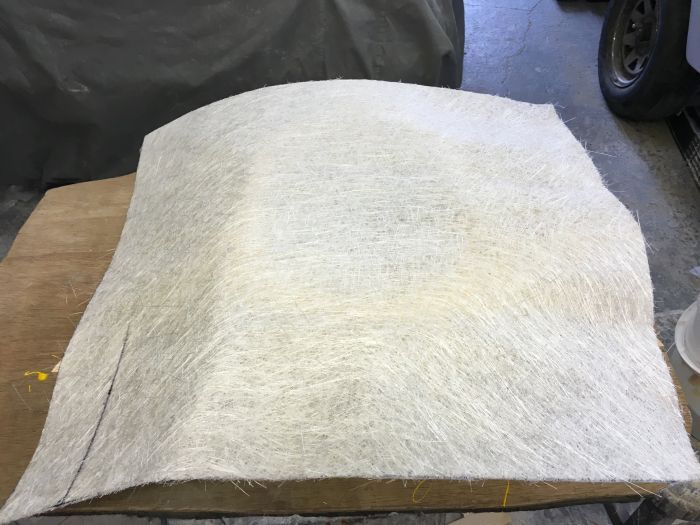
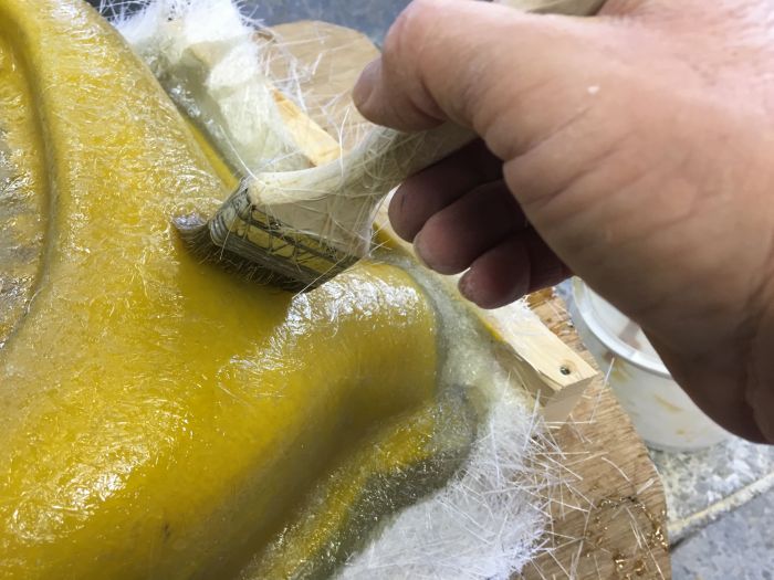
Then after wetting out the gel surface I began to stipple the laminate into position paying particular attention to the filter rebate.
By putting more resin than you need on at this point gravity gets a helping hand and starts to pull the glass down into position.
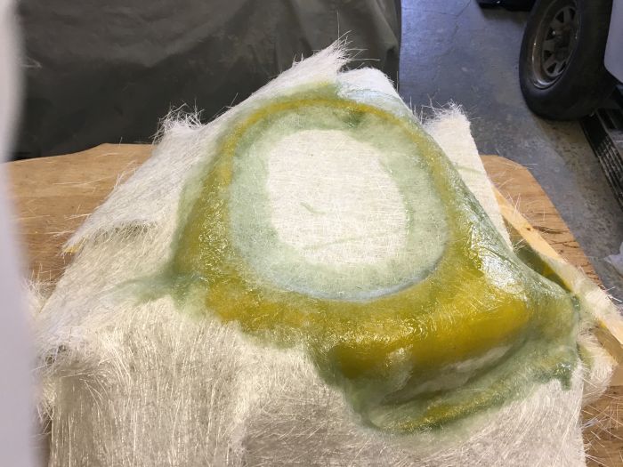
As this is happening ~i just work my way around the top and down the sides tearing the laminate as I need to so that the glass does not bunch up which you should be able to see in the picture.
In this next shot you can see how the weight of the resin literally pulls the glass down into the rebate and also how those little blocks of foam that were put in give the glass something to sit on rather than trying to fall off the internal edges help at this stage.
Once the outer face has been fully wet out it is possible to work on the inner rebate area.
Just gently easing the glass into place helps to lose the bubbles that you will obviously see in this picture
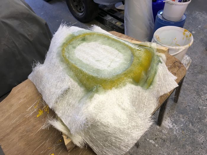
So repeating that process twice more it ends up looking like this.
Then after a gentle going over the whole mould with a fin roller I carefully stipple the brush that was used for laminating over the whole lot and suck up the excess resin and scrape that back into the bucket.
You can clearly see that there is too much resin at this point.
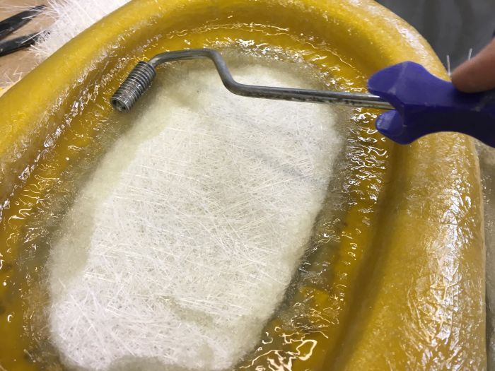
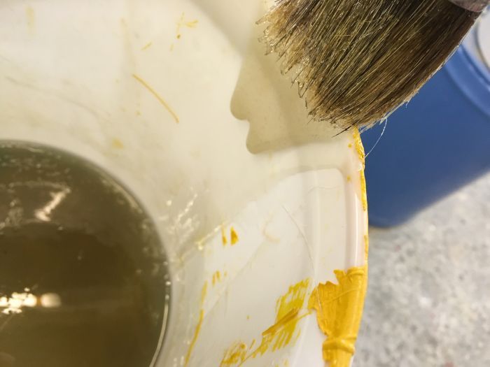
By doing this you dont end up with a resin rich moulding which is not a strong as a just the right amount of resin on the mould moulding.
Total glassing time 35 minutes.
This will be left now until tomorrow evening to cure and then the last three layers will go on.
By loading the sharper radii with gel the radii surfaces went form about 4mm overall to approximately 8 mm and this helped tremendously with getting the glass to roll over the top and into the corners at the bottom.
I know some have asked how to get over this problem in the past and hope that that question has now been answered with my drivel and the pics.
If anyone has any questions then please feel free to ask as what might be straightforward for a goon like me might not be so obvious to someone thinking of having a go at something like this for themselves.
Cup of tea time now!
cheers
P
I am going to use 6 layers of 600gsm (grams per square meter) and polyester resin.
This will in effect give me a final mould thickness of 9/10mm which will be perfect.
So I cut 6 sections 24"x 22" and the first picture shows the full sheet sitting on the top of the mould prior to any resin being applied.

Then after wetting out the gel surface I began to stipple the laminate into position paying particular attention to the filter rebate.
By putting more resin than you need on at this point gravity gets a helping hand and starts to pull the glass down into position.

As this is happening ~i just work my way around the top and down the sides tearing the laminate as I need to so that the glass does not bunch up which you should be able to see in the picture.

In this next shot you can see how the weight of the resin literally pulls the glass down into the rebate and also how those little blocks of foam that were put in give the glass something to sit on rather than trying to fall off the internal edges help at this stage.

Once the outer face has been fully wet out it is possible to work on the inner rebate area.

Just gently easing the glass into place helps to lose the bubbles that you will obviously see in this picture

So repeating that process twice more it ends up looking like this.

Then after a gentle going over the whole mould with a fin roller I carefully stipple the brush that was used for laminating over the whole lot and suck up the excess resin and scrape that back into the bucket.
You can clearly see that there is too much resin at this point.


By doing this you dont end up with a resin rich moulding which is not a strong as a just the right amount of resin on the mould moulding.
Total glassing time 35 minutes.
This will be left now until tomorrow evening to cure and then the last three layers will go on.
By loading the sharper radii with gel the radii surfaces went form about 4mm overall to approximately 8 mm and this helped tremendously with getting the glass to roll over the top and into the corners at the bottom.
I know some have asked how to get over this problem in the past and hope that that question has now been answered with my drivel and the pics.
If anyone has any questions then please feel free to ask as what might be straightforward for a goon like me might not be so obvious to someone thinking of having a go at something like this for themselves.
Cup of tea time now!
cheers
P
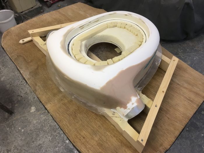
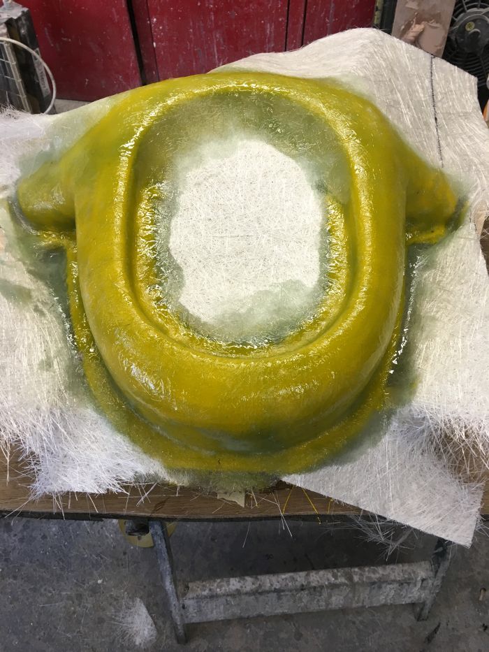
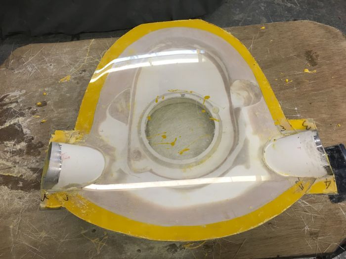
Got back out there again tonight and got the last three laminates on the top section.
Exactly the same procedure as yesterday but it is now much easier to get the glass to fall into the middle section as the radii are much greater.
This will now cure for about 24hrs and then it will be a quick trim of the excess turn the whole thing upside down remove the acrylic plate and glass the lower section in one hit (after it has been waxed of course)
Here's the completed top section.
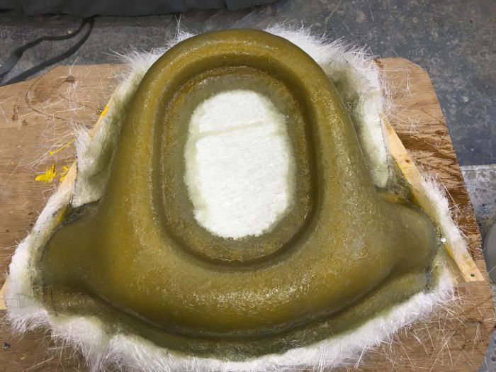
More again tomorrow ( he said hopefully )
cheers
P
Hi Reg
The oval filter top actually does work as a filter.
Its a K&N type of extreme filter top but it is covered in masking tape in the pictures just for protection.
As the air is drawn in from the intake at the back end of the bonnet this should act as a venturi for the front filters and vice versa.
The top filter looks really nice when its laid bare.
MMMmm Shiney.
Does this answer your question and have you checked your E mail tonight?
P
-
unstable load
- Top Dog
- Posts: 1278
- Joined: Mon May 04, 2009 6:53 am
hi All
Not managed much at all tonight as Mrs G had to go out for a couple of hours and I still had some real work to do for a customer before I could play for a little while.
I wont now get the bottom section glassed until Thursday evening at the earliest as I have agreed to go and work for a while on a mates project tomorrow night.
Anyway I waffle but here is tonights attempt
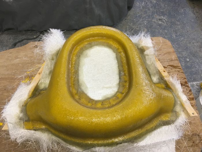
After removing most of the jig (some was well glassed together with the mould) I fired up the air hacksaw and buzzed the excess off.
Then it was just a case of final trimming and it ended up like this.
Next I need to sand back the edges until I can see the acrylic all the way around the bottom and then pop it off.
I promise it will all become as clear as mud as it progress's.
cheers
P
Not managed much at all tonight as Mrs G had to go out for a couple of hours and I still had some real work to do for a customer before I could play for a little while.
I wont now get the bottom section glassed until Thursday evening at the earliest as I have agreed to go and work for a while on a mates project tomorrow night.
Anyway I waffle but here is tonights attempt
After removing most of the jig (some was well glassed together with the mould) I fired up the air hacksaw and buzzed the excess off.

Then it was just a case of final trimming and it ended up like this.

Next I need to sand back the edges until I can see the acrylic all the way around the bottom and then pop it off.
I promise it will all become as clear as mud as it progress's.
cheers
P
I thought I might find you lurking around here somewhere.
As always life gets in the way of doing the things that you want to do for fun and now I find myself way behind where I wanted to be by this time.
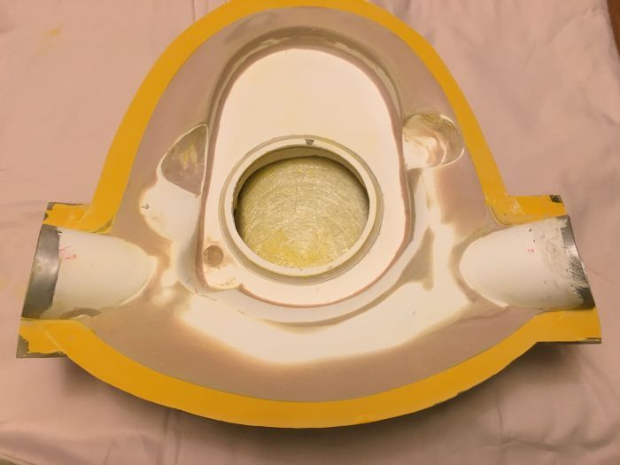
After sanding back the rough edges of the laminates and removing the acrylic I found to my disappointment that some gel had managed to get underneath the plate as it was applied and this led to me having to carefully sand back the excess but it didnt take too long to sort out.
As you will be able to see from the picture I now have a nice crisp edge between the gel and the plug which is how it should have been in the first place.
8 coats of wax have been applied but not really polished up much as there are lots of returns and angles on the lower section and I really need these to release fully once all is cured.
Having spoken to my tech guys I now have all of the info required to make this thing as heat proof as possible.
I have no idea what the temps are like under my bonnet when stuck in traffic so thought it would be best to check before actually making the real thing.
I will have to 'post cure' the unit once it has been bonded together and that process will be explained later once we get to that point.
I will also be using a much higher temperature rated resin along with a fire guard coating on the inside which will be sanded back smooth once that has cured.
If I get chance to get back out there this week then there will be more of my rambling but in the meantime this is all I have for you.
Thanks for the interest comments and questions.
cheers
P
As always life gets in the way of doing the things that you want to do for fun and now I find myself way behind where I wanted to be by this time.
After sanding back the rough edges of the laminates and removing the acrylic I found to my disappointment that some gel had managed to get underneath the plate as it was applied and this led to me having to carefully sand back the excess but it didnt take too long to sort out.
As you will be able to see from the picture I now have a nice crisp edge between the gel and the plug which is how it should have been in the first place.
8 coats of wax have been applied but not really polished up much as there are lots of returns and angles on the lower section and I really need these to release fully once all is cured.

Having spoken to my tech guys I now have all of the info required to make this thing as heat proof as possible.
I have no idea what the temps are like under my bonnet when stuck in traffic so thought it would be best to check before actually making the real thing.
I will have to 'post cure' the unit once it has been bonded together and that process will be explained later once we get to that point.
I will also be using a much higher temperature rated resin along with a fire guard coating on the inside which will be sanded back smooth once that has cured.
If I get chance to get back out there this week then there will be more of my rambling but in the meantime this is all I have for you.
Thanks for the interest comments and questions.
cheers
P
Hi Elliot
I completely understand and accept what you are saying and as such I feel that I really should use the higher spec resin and fire guard as this will be fixed directly to my motor.
As this is completely experimental I have to do the best that my abilities will afford and not to have a slumped and horrible mess under the bonnet after a good run.
I have not forgotten that I promised to send you some pictures more like I just have not had the time just lately.
As life seems to be getting in the way of me being able to do fun stuff I really would like to have the second section fully complete before the end of next week as work away beckons once again.
This would be fine as for the time away will allow the mould to cure and shrink and then once back home I can get cracking once more.
cheers
P
