
A tacho should receive a trigger from the -ve ie trigger side of the coil...you stated it was supplied from the 12v side ?
Have you tested the ecu's outputs as requested ?
Ignition circuitry with MoTeC
Moderator: phpBB2 - Administrators
-
stevieturbo
- Forum Contributor

- Posts: 3979
- Joined: Sat Nov 18, 2006 6:22 pm
- Location: Northern Ireland
Thanks for the pics. Nothing obvious there.
But the coil must get +12v from somewhere. What make/model is the ignition amp module? If I can find details of it might help me understand it.
I have seen revcounters connected to the coil positive. There will still be a pulse present there - but not as large as at the negative.
But the coil must get +12v from somewhere. What make/model is the ignition amp module? If I can find details of it might help me understand it.
I have seen revcounters connected to the coil positive. There will still be a pulse present there - but not as large as at the negative.
Dave
London SW
Rover SD1 VDP EFI
MegaSquirt2 V3
EDIS8
Tech Edge 2Y
London SW
Rover SD1 VDP EFI
MegaSquirt2 V3
EDIS8
Tech Edge 2Y
-
stevieturbo
- Forum Contributor
- Posts: 3979
- Joined: Sat Nov 18, 2006 6:22 pm
- Location: Northern Ireland
More wiring info here.
But still..testing needs done
http://www.motec.com.au/forum/viewtopic.php?f=6&t=3380
But still..testing needs done
http://www.motec.com.au/forum/viewtopic.php?f=6&t=3380
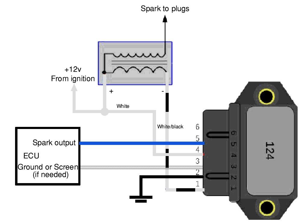
That suggests the module is a Bosch 0 227 100 124stevieturbo wrote:More wiring info here.
But still..testing needs done
http://www.motec.com.au/forum/viewtopic.php?f=6&t=3380
Pinouts are:-
1 = Coil negative output
2 = Power Ground
3 = Input screen (if used)
4 = 12V supply
5 = Spark input signal
6 = NC
(7 = NC)
Dave
London SW
Rover SD1 VDP EFI
MegaSquirt2 V3
EDIS8
Tech Edge 2Y
London SW
Rover SD1 VDP EFI
MegaSquirt2 V3
EDIS8
Tech Edge 2Y
-
stevieturbo
- Forum Contributor
- Posts: 3979
- Joined: Sat Nov 18, 2006 6:22 pm
- Location: Northern Ireland
I would still like to see a better test of the ecu outputs.
He's stated some voltages....which are unusual.
Again, a meter set to volts is not an ideal test, it would need to be something that can identify the fast voltage changes. Whether a dwell meter, frequency, scope etc.
A digital voltmeter should register some sort of change though, although a static reading of 1.6v or whatever it was just makes little sense.
And was the reading to ground, or across both wires ?
-
stevieturbo
- Forum Contributor
- Posts: 3979
- Joined: Sat Nov 18, 2006 6:22 pm
- Location: Northern Ireland
Your drawing would differ slightly from Motec's drawing for what is supposed to be the same amp.
At the minute the only thing that has changed has been the tacho...IMO disconnect this completely from the car and try again
New ignition amps do not appear to be expensive ( there's even one on ebay for £15 )
Jut try a new one with the tacho disconnected
At the minute the only thing that has changed has been the tacho...IMO disconnect this completely from the car and try again
New ignition amps do not appear to be expensive ( there's even one on ebay for £15 )
Jut try a new one with the tacho disconnected
Sorry, my error. The tacho was originally connected to coil positive, and is now required to be connected to coil negative. ECU outputs were tested as above: 5V at each of pins 12 and 24 with ignition on, which drops to 1.6V at pin 12 and negligible at pin 24 when cranking - both to battery earth strap.stevieturbo wrote:A tacho should receive a trigger from the -ve ie trigger side of the coil...you stated it was supplied from the 12v side ?
Have you tested the ecu's outputs as requested ?
Intermotor 15000. Maybe not the greatest quality, but I've tried 2 new ones, as well as the original. Agreed, baffled by the lack of 12V feed to either coil or amp.DaveEFI wrote:Thanks for the pics. Nothing obvious there.
But the coil must get +12v from somewhere. What make/model is the ignition amp module? If I can find details of it might help me understand it.
I have seen revcounters connected to the coil positive. There will still be a pulse present there - but not as large as at the negative.
-
stevieturbo
- Forum Contributor
- Posts: 3979
- Joined: Sat Nov 18, 2006 6:22 pm
- Location: Northern Ireland
And again, looking at the wiring diagram and the fact there are 2 wires leaving the ecu to the amp...the test should probably be conducted between those two wires.Number 7 wrote:Sorry, my error. The tacho was originally connected to coil positive, and is now required to be connected to coil negative. ECU outputs were tested as above: 5V at each of pins 12 and 24 with ignition on, which drops to 1.6V at pin 12 and negligible at pin 24 when cranking - both to battery earth strap.stevieturbo wrote:A tacho should receive a trigger from the -ve ie trigger side of the coil...you stated it was supplied from the 12v side ?
Have you tested the ecu's outputs as requested ?
But it is always worth testing to ground too.
So you're saying it's 5v engine not rotating ?
1.6v with the engine rotating ? measured how ? a multimeter on volts will not give an accurate picture although the fact the voltage has changed would indicate something is happening.
When you stop cranking again does this revert to 5v ?
IF...if that is what you're saying, then it sounds like the ecu is fine. But a better test would be dwell, pulse width, frequency..or a scope trace to prove without question what is happening. Although even an LED between the two terminals should show if it is pulsing correctly.
-
stevieturbo
- Forum Contributor
- Posts: 3979
- Joined: Sat Nov 18, 2006 6:22 pm
- Location: Northern Ireland
stevieturbo wrote:And again, looking at the wiring diagram and the fact there are 2 wires leaving the ecu to the amp...the test should probably be conducted between those two wires.Number 7 wrote:Sorry, my error. The tacho was originally connected to coil positive, and is now required to be connected to coil negative. ECU outputs were tested as above: 5V at each of pins 12 and 24 with ignition on, which drops to 1.6V at pin 12 and negligible at pin 24 when cranking - both to battery earth strap.stevieturbo wrote:A tacho should receive a trigger from the -ve ie trigger side of the coil...you stated it was supplied from the 12v side ?
Have you tested the ecu's outputs as requested ?
But it is always worth testing to ground too.
So you're saying it's 5v engine not rotating ? Yes, but only with the multiplug not connected to the amp
1.6v with the engine rotating ? measured how ? a multimeter on volts will not give an accurate picture although the fact the voltage has changed would indicate something is happening. Yes, 1.6V from ECU pin 12 when cranking with amp multiplug in, using a digital multimeter from . Negligible output from ECU pin 24 when cranking.
When you stop cranking again does this revert to 5v ? No, mutiplug connected at amp this stays at 1.6V from ECU pin 12, negligible from ECU pin 24.
IF...if that is what you're saying, then it sounds like the ecu is fine. But a better test would be dwell, pulse width, frequency..or a scope trace to prove without question what is happening. Although even an LED between the two terminals should show if it is pulsing correctly. Will try to test dwell.
-
stevieturbo
- Forum Contributor
- Posts: 3979
- Joined: Sat Nov 18, 2006 6:22 pm
- Location: Northern Ireland
