
Hi all need a bit of help.....
Im currently building an a ac cobra replica project.the engine is a rover v8 3.5 but worked to a 4.0 and when i bought the car it was rolling and poor starting because the water pipe connection on the front of the inlet manifold was obstructing the dizzy...
ive took the dizzy out and tried to rectify the problem however now ive put the dizzy back in..ive forgotten the firing order can anyone help pleaseeee.
As looking on the internet and following the diagrams the car wont start at all.but if i do the leads back to front it attempts to start..
what i need is the no1 cylinder as ive no timing marks n the pulley and then the firing order of leads to dizzy
thankyou in advance and much appreciated.ill upload some pictures of the project later today and also of the engine.my engine has the dizzy at the front
firing and timing
Moderator: phpBB2 - Administrators
Are you sure that your damper wheel has no timing marks? All of the ones that I have seen do have at least TDC and a few other marks. They can be tricky to see as can the pointer that needs to line up with the marks.
Without timing marks it is going to be a total guess as to what timing you are running and this really is not good enough. In my humble the solution would be to create your own marks or use timing tape, even then you are still going to have to find true TDC so that you can stick the tape on the wheel in the correct position.
Once you are able to work out what position the crank is in then setting up the timing is not all that hard. There is a long winded process that I have outlined below, it is long winded to ensure that you get everything setup correctly.
1. Remove spark plugs so that the engine is easy to turn over using a socket on the end of the crank.
2. Remove the rocker cover for the 'odd' cylinder bank. (This is the bank nearest the dizzy)
3. Get someone to slowly turn the engine over clockwise whilst you watch the valves, it also helps if you poke a screw driver down the plug hole of cylinder number 1 so you know what the piston is doing. (Cyl 1 is nearest the dizzy). As the engine is turned over using the socket watch for the inlet valve opening. (You can work out which is the inlet valve and which is the exhaust valve by looking at the inlet manifold and exhaust). As the inlet valve opens the piston should be on its way down the bore. As the engine is turned the piston will start on its way up the bore and the inlet valve will close. Stop the rotation of the crank when the piston is at 10 degrees before TDC. This will have placed the engine in the correct position for the firing point of cylinder number 1. i.e. with will be on the compression stroke and just before TDC.
4. I will assume that you have an electronic dizzy here, a points system has no place on any decent engine. Take the cap off the dizzy and pull off the rotor arm so that you can see the 'spikey' reluctance wheel that sits under the rotor arm. You need to twist the dizzy so that one of the spikes on the wheel has just gone past the centre of the pickup coil. (1mm past the very centre of the metal part of the coil). Note that you can twist the dizzy or even remove it and re-fit it an different position if you wish, it does not care! Also note that the dizzy turns clockwise.
5. Tighten the clamp bolt so that you can only move the dizzy with some effort.
6. Refit the rotor arm and note where it is pointing, refit the cap and note which High Tension post (HT post) on the cap is above the tip of the rotor arm. This post will be for cylinder number 1. Following round in clockwise direction the firing order i.e. 18436572. The tip of the rotor arm may be a little way past the HT post but it should be pretty near it.
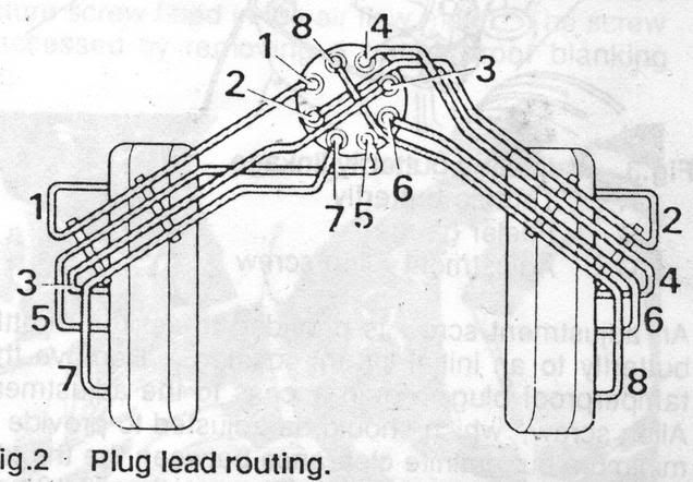
7. Refit all the spark plugs and connect the leads up to the plugs and the rocker cover. Note the firing order above. Also note how the cylinders are number. number 1 is nearest the dizzy, just behind it is number 3, then 5 then 7. The other cylinder bank starts with 2 at the front, then 4, then 6 then 8.
The engine should now fire up, you will then need to set the timing with a strobe, the actual figures that you should go for is a subject in its own right, to a degree it depends on what induction system you are using....Eddy carb, SU's EFI etc. The all 'in-figure' for your 4.0 engine should be around 32-34 degrees I would have thought. Once the timing is setup with the strobe the dizzy clamp bolt should be full tightened.
If you are bored have a read of this, ”Setting up a standard Lucas RV8 ignition system for maximum performance”………………….
http://how-to-build-a-pilgrim-sumo.wiki ... by-members
Without timing marks it is going to be a total guess as to what timing you are running and this really is not good enough. In my humble the solution would be to create your own marks or use timing tape, even then you are still going to have to find true TDC so that you can stick the tape on the wheel in the correct position.
Once you are able to work out what position the crank is in then setting up the timing is not all that hard. There is a long winded process that I have outlined below, it is long winded to ensure that you get everything setup correctly.
1. Remove spark plugs so that the engine is easy to turn over using a socket on the end of the crank.
2. Remove the rocker cover for the 'odd' cylinder bank. (This is the bank nearest the dizzy)
3. Get someone to slowly turn the engine over clockwise whilst you watch the valves, it also helps if you poke a screw driver down the plug hole of cylinder number 1 so you know what the piston is doing. (Cyl 1 is nearest the dizzy). As the engine is turned over using the socket watch for the inlet valve opening. (You can work out which is the inlet valve and which is the exhaust valve by looking at the inlet manifold and exhaust). As the inlet valve opens the piston should be on its way down the bore. As the engine is turned the piston will start on its way up the bore and the inlet valve will close. Stop the rotation of the crank when the piston is at 10 degrees before TDC. This will have placed the engine in the correct position for the firing point of cylinder number 1. i.e. with will be on the compression stroke and just before TDC.
4. I will assume that you have an electronic dizzy here, a points system has no place on any decent engine. Take the cap off the dizzy and pull off the rotor arm so that you can see the 'spikey' reluctance wheel that sits under the rotor arm. You need to twist the dizzy so that one of the spikes on the wheel has just gone past the centre of the pickup coil. (1mm past the very centre of the metal part of the coil). Note that you can twist the dizzy or even remove it and re-fit it an different position if you wish, it does not care! Also note that the dizzy turns clockwise.
5. Tighten the clamp bolt so that you can only move the dizzy with some effort.
6. Refit the rotor arm and note where it is pointing, refit the cap and note which High Tension post (HT post) on the cap is above the tip of the rotor arm. This post will be for cylinder number 1. Following round in clockwise direction the firing order i.e. 18436572. The tip of the rotor arm may be a little way past the HT post but it should be pretty near it.
7. Refit all the spark plugs and connect the leads up to the plugs and the rocker cover. Note the firing order above. Also note how the cylinders are number. number 1 is nearest the dizzy, just behind it is number 3, then 5 then 7. The other cylinder bank starts with 2 at the front, then 4, then 6 then 8.
The engine should now fire up, you will then need to set the timing with a strobe, the actual figures that you should go for is a subject in its own right, to a degree it depends on what induction system you are using....Eddy carb, SU's EFI etc. The all 'in-figure' for your 4.0 engine should be around 32-34 degrees I would have thought. Once the timing is setup with the strobe the dizzy clamp bolt should be full tightened.
If you are bored have a read of this, ”Setting up a standard Lucas RV8 ignition system for maximum performance”………………….
http://how-to-build-a-pilgrim-sumo.wiki ... by-members
If it's a DLM dizzy, with the amp on the side, there are different versions. The position of the vacuum unit relative to the amp. The amp is normally at the front for best cooling, and the vacuum unit position chosen to clear the hoses. Think there are two - Range Rover and SD1. Also to give the very best plug lead layout to prevent cross firing.
Last edited by DaveEFI on Wed Jul 20, 2016 11:51 am, edited 1 time in total.
Dave
London SW
Rover SD1 VDP EFI
MegaSquirt2 V3
EDIS8
Tech Edge 2Y
London SW
Rover SD1 VDP EFI
MegaSquirt2 V3
EDIS8
Tech Edge 2Y
Cylinders 5 and 7 are traditionally the ones that you need to be careful with when talking about cross cylinder firing but having said that I'm not convinced that any of the standard Rover/Lucas systems can produce enough HT to induce a cross cylinder misfire anyway. I have seen loads of HT lead setups where the owner of the car has made the leads 'look nice' by running them in parallel for quite some distance without having a misfire. People even bundle the hold set of leads up together with cable ties! 
-
craigy2210
- Newbie

- Posts: 5
- Joined: Wed Jul 20, 2016 12:01 am
Thank you
Thanks for the explanation was a nightmare before sidecar and Dave posted there help.. And a great help they were as the car started almost instantly sounding amazing. I'll post some pics on here of the build thanks again to everyone..


Hi Craigy, thanks for coming back and posting up your results, its always nice to know that things have worked out OK. I see that you are building a Pilgrim Sumo, it would well worth becoming a member of the Cobra forum if you are not already....
http://www.cobraclub.com/forum/forum.php
I can see that you are using the older style of top wishbones, there is a chassis mod that you should do with these wishbones in order to increase the camber angle so that the steering self centres. There a bumpsteer mod that totally transform the handling of the car that can be done too!
Finally I would not lift an engine by the rocker shafts but that's just me!
