I'm intending making a cam position sensor out of an RV8 dizzy - a DLM - and would welcome tips so I don't just re-invent the wheel. Only really have hand tools - no lathes or surface grinders, etc. Would like it as small as practicable, though.
Have some Allegro ATS682 hall effect gear tooth sensors in stock so would be nice to use one of those. The spec sheet says approx 1-3mm air gap will be ok.
Cam position sensor
Moderator: phpBB2 - Administrators
-
stevieturbo
- Forum Contributor

- Posts: 3979
- Joined: Sat Nov 18, 2006 6:22 pm
- Location: Northern Ireland
Really the easiest, is just to use OEM dizzy trigger setup and remove teeth from the trigger as required.
But obviously this still leaves a full size dizzy up top
Presumably it's an RV8 that needs to retain a dizzy shaft to drive the oil pump ?
If so, obviously this is going to add machining requirements etc
ie housing, shaft, bearings, then some sort of tooth setup up top and a mount for it all.
If the sensor you're using is a long threaded type.
As a temp measure before I fitted the proper camwheel with a dizzy on my LS, I "improvised" a phase trigger using a hall sensor pointed at the tip of the roller rocker.
It was simple, only required work to the rocker cover to install and seemed to work ok.
I opted to ignore cam signal once it was sync'd up, as knew overall it wasnt a great setup. But it was cheap quick and easy to make.
If doing that approach again I'd probably aim the sensor directly onto the top of the spring and if you're using steel spring retainers this should be very easy.
Mine are Ti so this did hamper the signal a little hence I opted for the steel roller on the rocker instead.
I've made a stumpy drive, so can cut down a dizzy with hand tools.
The ATS682 sensors I have are just a bare IC - no mounting. About the size of a little finger nail.
My idea is to gut the dizzy, and cut down the plate attached to the main shaft that the springs fit to into a suitable single 'spike'
Cut off the shaft above that, cut the body just above than and make a flat top from ally.
Dave
London SW
Rover SD1 VDP EFI
MegaSquirt2 V3
EDIS8
Tech Edge 2Y
London SW
Rover SD1 VDP EFI
MegaSquirt2 V3
EDIS8
Tech Edge 2Y
I don't know if its any help but what I did to make my cam position sensor was I used an old points distributor (though you could use an electronic distributor) and gutted the all the internals (advance mech, etc) and made a post fitted with a half moon disc that is fitted to the original distributor shaft this then triggers an old luminition optronic sensor (this works fine on the 5Volt feed) to give me my cam position.
3.5l v8 Triumph Spitfire
351 ci Cleveland powered 71 mach1
351 ci Cleveland powered 71 mach1
If you want a really accurate Cam position then using a dizzy may not be the best idea given the amount of slack in the timing chain and associated drive.
There is a CAM position sensor on the GEMS engines I believe might be worth investigating if that can be used
There is a CAM position sensor on the GEMS engines I believe might be worth investigating if that can be used
Range Rover 630R or otherwise known as the Money Pit
MS2 with switch MAPS for LPG
Techedge Wideband Sensor
MS2 with switch MAPS for LPG
Techedge Wideband Sensor
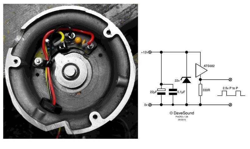
This what I ended up with. Zero cost since I already had all the bits. Removed everything which came off the dizzy, and cut down the plate on the end of the main shaft to make a tooth. Sawed off the top if the casing to accept a flat plate.
Dave
London SW
Rover SD1 VDP EFI
MegaSquirt2 V3
EDIS8
Tech Edge 2Y
London SW
Rover SD1 VDP EFI
MegaSquirt2 V3
EDIS8
Tech Edge 2Y