

Thought I would start a new thread with flow figures so we have all the data in one place these were posted by Wotland a while back
Its a pity that the test depression is not stated as without it the figures do not mean very much but hopefuly that will become apparent in due course, however from the work done on the bench today it would look like the figures are at 28" or above
Some flow bench datas :
Valve Lift --Buick 300 In. valve 1.775--Buick 300 Exh. valve 1.500
0.100................... 66....................................... 47
0.150................... 99....................................... 82
0.200................. 129...................................... 104
0.250................. 155...................................... 119
0.300................. 174...................................... 130
0.350................. 187...................................... 139
0.400................. 191...................................... 146
0.450 .................194.............................. ........ 150
0.500................. 196...................................... 152
0.550................. 200...................................... 153
Valve lift--Rover genuine In valve 1.575--Rover genuine Exh. valve 1.350
0.200................. 92.2..................................... 72.2
0.300................ 132.6..................................... 85.7
0.400................ 143.3..................................... 89.5
0.450 ................145.7............................. ........ 90.5
0.500................ 147.7 .....................................91.3
0.550................ 148........................................ 91.6
Valve lift--Rover Stage4 In. valve 1.700--Rover Stage4 Exh. valve 1.500
0.200................ 101.4 .....................................80.1
0.300................ 143.9 ....................................106.6
0.400................ 177.1 ....................................127
0.450................ 180.6 ....................................134.3
0.500................ 181 .......................................139.7
0.550................ 181 .......................................142.8
I have also found some interesting comments regarding the Peter Burgess figures in the Speedpro book - sounds like Peters bench flows low due to a design flaw and that the rover figures should actually be about 20% higher
The figures I ran on my bench today for the P6 were higher than his SD1 figures so I think we are on the right track.
The speedpro figures for a stock SD1/Moded Sd1/RaceSD1 are
all at 25" H2O
100.....37.3.....42.1.....46.0
200.....72.9.....83.6.....93.4
300.....97.1.....111.4.....128.0
400.....111.1.....123.6.....147.6
500.....113.2.....128.5.....157.0
600.............................162.4
If anyone has any other figures on any of the RV8 heads please make them available
Andrew
Cylinder head flow figures
Moderator: phpBB2 - Administrators
Cylinder head flow figures
Last edited by Darkspeed on Mon Dec 21, 2009 1:30 pm, edited 1 time in total.
4.5L V8 Ginetta G27

Already given it a test - not the quickest with Excel but have plotted P6 against Stg 1 3.9. - I will convert it to a jpg tomorrow and post it.
Unless the flows are from the same bench or the figures are reliable and have a known depression, placing them on the same graph would just confuse things.
Andrew
Unless the flows are from the same bench or the figures are reliable and have a known depression, placing them on the same graph would just confuse things.
Andrew
ChrisJC wrote:For ease of reference, is it possible to present the results in a graph?
Chris.
4.5L V8 Ginetta G27
-
HairbearTE

- Guru

- Posts: 870
- Joined: Sat Nov 18, 2006 12:27 am
- Location: Melton Mowbray
I agree. Obviously for the most reliable reference it would be ideal for all the data to be taken from the same bench.Darkspeed wrote:Already given it a test - not the quickest with Excel but have plotted P6 against Stg 1 3.9. - I will convert it to a jpg tomorrow and post it.
Unless the flows are from the same bench or the figures are reliable and have a known depression, placing them on the same graph would just confuse things.
Andrew
ChrisJC wrote:For ease of reference, is it possible to present the results in a graph?
Chris.
I am happy enough that my bench has the capacity and the potential accuracy (Operator dependent  ) to be up to the task.
Quite sure you would very popular if you made a Merlin head available for appraisal along side all the others that are being lined up.
Where on this fine island are you?
Andrew
Quite sure you would very popular if you made a Merlin head available for appraisal along side all the others that are being lined up.
Where on this fine island are you?
Andrew
4.5L V8 Ginetta G27
Calibrating and taking the temperature readings etc and setting the bench up takes about 20minutes.
It takes another 20-30 mins or so to set the head up on the adaptor and make sure that its sealed correctly, set the dial gauges and the inlet radius clay etc.
Taking the flow readings is pretty painless with the system I have as its all digital.
A couple of runs takes about half an hour.
Bit like a power run on a rolling road to be honest and like a RR its sorting out the detials and doing any investigations thrown up by anomolies that chew up the time.
Taking the numbers on a stock or an aftermarket set of heads is simple - sticking the data on a graph and printing should be a piece of cake once I get myself up to speed with Excel or buy some more software.
I will do a full pictorial flowing a head message when I get the adaptors and some nice clean pretty heads to play with.
Andrew
mgbloke wrote:Im 180 miles away in Wiltshire.
How long does it take to do the flow test and how is it done?
Mark
4.5L V8 Ginetta G27
Basic graph - not calibrated flows just a couple of rough tests to get some figures into the software - But hoping to get a bit better with Excel and dress them up (although I am more for information than presentation)
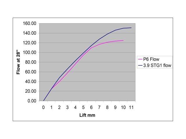
I did back to back the peak flows though after calibrating the bench and the figures are good.
Quite chuffed with 22% peak flow increase over the P6 heads.
I did back to back the peak flows though after calibrating the bench and the figures are good.
Quite chuffed with 22% peak flow increase over the P6 heads.
ChrisJC wrote:For ease of reference, is it possible to present the results in a graph?
Chris.
4.5L V8 Ginetta G27
No sweat Mark I quite understand that - plenty of time with this project it's not going to happen overnight and we will get a set on the bench at some point in the future.
May even call RS and see if fancy taking part in this head shoot out and send a head up for testing - may be worthwhile for them and the worst they can do is say no.
Andrew
May even call RS and see if fancy taking part in this head shoot out and send a head up for testing - may be worthwhile for them and the worst they can do is say no.
Andrew
mgbloke wrote:Andrew
Although I am curious to know how much the Merlins flow, as I have already bought a set its not going to help me that much. Cant really justify £50 in fuel to find out. Shame we are not nearer to each other.
Mark
4.5L V8 Ginetta G27

Been playing with the bench today as I have manufactured a mounting fixture and sleeved it to 94mm bore so it accurately represents the operating condition on an engine - it also has dowels to locate heads the same way every time so I now have excellent repeatability.
Today I was seeing what difference the standard parts make and running some comparisons and thought I would pass on a simple tuning tip
A 30 degree cut back on the back of a standard valve increases flow in comparison to a standard valve by:-
All flows @28"
2mm - 38 to 42 CFM + 10%
4mm - 76 to 82 CFM + 8%
6mm - 109 to 116 CFM + 6%
At higher lifts there is hardly any difference as the valve/seat area becomes less critical.
Another thing was that in a ported head there is very little difference between a waisted stem valve and a stock valve.
Andrew
4.5L V8 Ginetta G27
