
If your factory ecu's are using a VR sensor, you cant just randomly change this for a hall sensor. The ecu will not understand the new signal.Spongo wrote:Aha that could be the problem as I am sharing the sensor with 2 ECU's
I will give the Hall sensor a go I think
Hall effect CPS
Moderator: phpBB2 - Administrators
-
stevieturbo
- Forum Contributor

- Posts: 3979
- Joined: Sat Nov 18, 2006 6:22 pm
- Location: Northern Ireland
Many thousands are using a VR sensor OK with MS. If yours is giving problems, there will be a reason. The VR sensor produces a large signal level at higher revs - much the same as a hall. Main difference is it's an approx sine wave, while the hall is square. But the VR input converts that variable voltage sine wave into a constant level square wave (pulses) anyway. But it does need to be adjusted correctly.
Dave
London SW
Rover SD1 VDP EFI
MegaSquirt2 V3
EDIS8
Tech Edge 2Y
London SW
Rover SD1 VDP EFI
MegaSquirt2 V3
EDIS8
Tech Edge 2Y
-
stevieturbo
- Forum Contributor
- Posts: 3979
- Joined: Sat Nov 18, 2006 6:22 pm
- Location: Northern Ireland
Hall sensor voltage will not change with engine speed. It is a fixed off/on square wave and the fixed voltage output will depend on sensor. Usually switching between either 5v or 0v regardless of power supply voltage which could be say 5-12vDaveEFI wrote:Many thousands are using a VR sensor OK with MS. If yours is giving problems, there will be a reason. The VR sensor produces a large signal level at higher revs - much the same as a hall. Main difference is it's an approx sine wave, while the hall is square. But the VR input converts that variable voltage sine wave into a constant level square wave (pulses) anyway. But it does need to be adjusted correctly.
VR typically recognises a correct tooth trigger when the voltage exceeds a certain threshold, then falls through the zero line ( for a falling edge setup which is most common )
I would not be sharing the VR signal between two ecu's though if at all possible. If you need to do that, add another VR sensor for the MS alone.
But again, scope the sensor output to see exactly what the signal is like.
The VR sensor only produces a simple near sine wave. It's the electronics of the VR input which finds the zero crossing point and converts to pulses which the processor can read.
The processor on MS expects to see pulses of approx 5v peak to peak. The VR input circuit, correctly adjusted, produces that pretty well regardless of the voltage from the sensor.
The Honeywell hall sensor I mentioned is an open collector type. That allows its internal electronics to be run off one voltage - say regulated 5 volts, but the output to switch say 12 volts. But there are all sorts of options out there.
Dave
London SW
Rover SD1 VDP EFI
MegaSquirt2 V3
EDIS8
Tech Edge 2Y
London SW
Rover SD1 VDP EFI
MegaSquirt2 V3
EDIS8
Tech Edge 2Y
-
stevieturbo
- Forum Contributor
- Posts: 3979
- Joined: Sat Nov 18, 2006 6:22 pm
- Location: Northern Ireland
In reality it sounds like the MS wants a hall input then, and is just trying to convert the VR signal instead of accepting and understanding it. In that case he would be better using a hall sensor for the MSDaveEFI wrote:The VR sensor only produces a simple near sine wave. It's the electronics of the VR input which finds the zero crossing point and converts to pulses which the processor can read.
The processor on MS expects to see pulses of approx 5v peak to peak. The VR input circuit, correctly adjusted, produces that pretty well regardless of the voltage from the sensor.
The Honeywell hall sensor I mentioned is an open collector type. That allows its internal electronics to be run off one voltage - say regulated 5 volts, but the output to switch say 12 volts. But there are all sorts of options out there.
All actual digital processors only understand pulses. So all will have some form of conditioning circuit to convert the sine wave from a VR sensor to pulses. Of course if you were making millions of them, it could be on board the processor chip. But no real advantage in doing that other than cost in mass production.
I'll repeat what I said earlier. Hall sensors are far more complicated than VR, and have to operate in a hostile (hot) environment. So are generally less reliable.
I'll repeat what I said earlier. Hall sensors are far more complicated than VR, and have to operate in a hostile (hot) environment. So are generally less reliable.
Dave
London SW
Rover SD1 VDP EFI
MegaSquirt2 V3
EDIS8
Tech Edge 2Y
London SW
Rover SD1 VDP EFI
MegaSquirt2 V3
EDIS8
Tech Edge 2Y
-
stevieturbo
- Forum Contributor
- Posts: 3979
- Joined: Sat Nov 18, 2006 6:22 pm
- Location: Northern Ireland
A lot of ecu's simply allow you to set a voltage threshold the VR needs to exceed, and fall through for a valid signal. No dedicated conditioners with fixed parameters required. It just makes it far more flexible and easy to set up.DaveEFI wrote:All actual digital processors only understand pulses. So all will have some form of conditioning circuit to convert the sine wave from a VR sensor to pulses. Of course if you were making millions of them, it could be on board the processor chip. But no real advantage in doing that other than cost in mass production.
I'll repeat what I said earlier. Hall sensors are far more complicated than VR, and have to operate in a hostile (hot) environment. So are generally less reliable.
And plenty of OEM use hall sensors for both crank and cam, and they are reliable. As said, it would be best to use an OEM sensor for these very reasons than any generic aftermarket type sensor where you are using it in an environment it was never intended.
-
stevieturbo
- Forum Contributor
- Posts: 3979
- Joined: Sat Nov 18, 2006 6:22 pm
- Location: Northern Ireland
DTA offers no ability do adjust trigger thresholds...IMO that is a bad thing and does limit how versatile the trigger setup can beDaveEFI wrote:I've seen some generic VR input circuits with no adjustments at all. But they all do much the same thing in the end. Convert an analogue signal into digits the processor can read.
That said, they did it deliberately so as not to confuse people. Sometimes simplifying things is a good thing, sometimes it is not.
But then they do for the most part tell you which sensors they know works perfectly with their setup, so it's easy to make it all work without any knowledge.
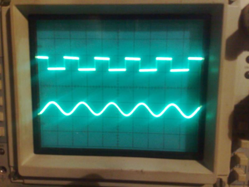
The two adjustment pots on the MS vr sensor seem to cause more confusion than just about anything else. Although that circuit often gets blamed for a fault elsewhere. I like to look at the output of the VR sensor and output on the VR input circuit at the same time with a dual beam scope. It's then obvious what they are doing.
This is a pic of my scope showing the output of a VR sensor on the lower trace, and the input to the processor (post VR input circuit) on the top.
Top trace is 5v per division, bottom 1v.
This is a pic of my scope showing the output of a VR sensor on the lower trace, and the input to the processor (post VR input circuit) on the top.
Top trace is 5v per division, bottom 1v.
Dave
London SW
Rover SD1 VDP EFI
MegaSquirt2 V3
EDIS8
Tech Edge 2Y
London SW
Rover SD1 VDP EFI
MegaSquirt2 V3
EDIS8
Tech Edge 2Y
-
stevieturbo
- Forum Contributor
- Posts: 3979
- Joined: Sat Nov 18, 2006 6:22 pm
- Location: Northern Ireland
A faster sampling rate would give a more defined trace for the VR signal.
The falling edge is generally faster than the rising, likewise at either peak instead of that smooth curve it would usually be sharper. Although the low rpm/voltage may also be partly to do with that
But at least you can determine voltage thresholds there and equally important see that the trace is clean with no interference.
If VR signal wiring passes by any HT leads etc, that can cause problems with some setups
Sorry - the point I was making is you adjust the pots for a nice clean square wave.That pic was taken on the bench.
Obviously on the car the signal from the VR sensor may not be as clean - but it's the output from the VR circuit which is important, as that's what the processor has to read.
Obviously on the car the signal from the VR sensor may not be as clean - but it's the output from the VR circuit which is important, as that's what the processor has to read.
Dave
London SW
Rover SD1 VDP EFI
MegaSquirt2 V3
EDIS8
Tech Edge 2Y
London SW
Rover SD1 VDP EFI
MegaSquirt2 V3
EDIS8
Tech Edge 2Y
-
stevieturbo
- Forum Contributor
- Posts: 3979
- Joined: Sat Nov 18, 2006 6:22 pm
- Location: Northern Ireland
That's the thing though, that aspect seems to be unique to MS.DaveEFI wrote:Sorry - the point I was making is you adjust the pots for a nice clean square wave.That pic was taken on the bench.
Obviously on the car the signal from the VR sensor may not be as clean - but it's the output from the VR circuit which is important, as that's what the processor has to read.
No other ecu I've come across requires the user to do that.
Depends on the version of MS. IIRC, the MicroSquirt has no adjustments. There are also aftermarket input boards available which have no adjustments.
I've no experience of either.
MS is designed to allow a user choice of the widest range of sensors possible.
They could easily restrict it to one or two they specify and have no adjustments.
MS is designed for DIY installation and as such does require the installer to learn up on the basics. Or pay someone else to do it for you.
Dave
London SW
Rover SD1 VDP EFI
MegaSquirt2 V3
EDIS8
Tech Edge 2Y
London SW
Rover SD1 VDP EFI
MegaSquirt2 V3
EDIS8
Tech Edge 2Y
