
Hi Guys,
I have a 1992 4.2 RV8 that I am retro fitting a twin SU manifold to - the EFi coolant flow is easy to follow with the external pipes running back to the heater matrix, and the bypass circuit through the front heating pipes.
This engine has the very tall water pump housing (I think it's the 'long' version) which has two outlets out the back of the water pump, one of which is closed off. This is completely different to the earlier SD1 V8 I have sat at the back of the workshop.
The older SU manifold has its heater hoses pipes under the manifold and out of the the back of the manifold, and with the bypass tube built into the older thermostat housing I'm feeling a bit thick on figuring this out.
Has anyone done this? I am trying to figure out the bypass circuit and routing for the heater.
Any advice appreciated!
Converting 4.2 EFi to SU Carb Manifold - Coolant Paths.
Moderator: phpBB2 - Administrators

What I think you need to do is to 'unblock' the blocked stub on the rear of the water pump housing. Both of those stubs are returns.
Connect one to the thermostat bypass (the stub below and to the right of the thermostat housing), and the other to the long pipe that runs underneath the inlet manifold.
Then connect the heater to the two pipes on the rear of the inlet manifold.
The water circulation path is this:
From the pump rearwards through the block
Up from the block into the heads at the rear
Forwards through the heads
Into the front of the inlet manifold. There it splits 3 ways:
1. Through the thermostat, through the rad, and back to the pump.
2. Through the thermostat bypass straight back to the pump
3. Rearwards through the inlet manifold, out of the back, through the heater, then back to the pump via the long pipe under the inlet manifold.
Don't forget to connect the small pipe at the very top of the inlet manifold to either the top of the rad, or to the header tank as that is a vent to stop air building up in the manifold.
Chris.
--
Series IIA 4.6 V8
R/R P38 4.6 V8
R/R L405 4.4 SDV8
Series IIA 4.6 V8
R/R P38 4.6 V8
R/R L405 4.4 SDV8
Chris,
You're definitely the guru for me!
Your explanation printed out, a large cup of tea and staring at the new engine and older manifold for a whilst helped the penny drop and I see the two coolant circuits now clear as day - brilliant.
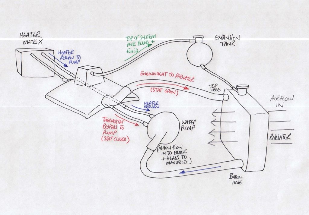
I need to take the water pump off again to safely drill out the second inlet on the back of the pump housing, then I can complete the build with peace of mind - I did a rough sketch to check my learning and have linked that here to show you what the plans is and hope it'll help someone in future, apologies though for the crap draughtsmanship;
http://i172.photobucket.com/albums/w22/ ... wkqybi.jpg
The only thing I'll add to this is a heater bypass valve - the heater I am fitting is just a matrix with a fan so I'll need to be able to control the flow through that matrix without affecting the flow out of the inlet manifold back to the pump - I have a cable operated bypass valve that will do that and will mount under the air box behind the manifold, top job.
(I'll get that photo CD off to you in the morning, apologies for the delay).
You're definitely the guru for me!
Your explanation printed out, a large cup of tea and staring at the new engine and older manifold for a whilst helped the penny drop and I see the two coolant circuits now clear as day - brilliant.
I need to take the water pump off again to safely drill out the second inlet on the back of the pump housing, then I can complete the build with peace of mind - I did a rough sketch to check my learning and have linked that here to show you what the plans is and hope it'll help someone in future, apologies though for the crap draughtsmanship;
http://i172.photobucket.com/albums/w22/ ... wkqybi.jpg
The only thing I'll add to this is a heater bypass valve - the heater I am fitting is just a matrix with a fan so I'll need to be able to control the flow through that matrix without affecting the flow out of the inlet manifold back to the pump - I have a cable operated bypass valve that will do that and will mount under the air box behind the manifold, top job.
(I'll get that photo CD off to you in the morning, apologies for the delay).
Your drawing is spot on!
Are you planning on using a Series III radiator with expansion bottle?
The whole header tank / expansion bottle thing is a bit of a can of worms!
On my Landie, I have a heater like you describe. To manage the hot / cold aspect, I just shut off the water flow through the heater. There is still the thermostat bypass / thermostat circuit, so coolant will always circulate. The only thing is that it won't circulate rearwards through the inlet manifold, but I never found that to be an issue.
Chris.
--
Series IIA 4.6 V8
R/R P38 4.6 V8
R/R L405 4.4 SDV8
Series IIA 4.6 V8
R/R P38 4.6 V8
R/R L405 4.4 SDV8
I have a Series II/III radiator which has been re-cored, but might not use the expansion bottle if I go for waterless coolant on the refill as that stuff doesn't increase pressure over about 5psi so the space in the top of the rad should suffice for expansion.
The guys who provided the conversion kit say that the radiator size will be fine even with normal coolant so long as the viscous fan is good, or fit an electric pact type if short of space.
The bypass valve I mentioned is an independent gizmo operated by a bowden cable for flow on or off. With the matrix flow shut off it runs the coolant straight back to the return line, and should give a degree of adjustment through the flow and the fan speed inside.
Hi
with reference the waterless coolant, I have only seen two engines that have used it but in both cases on taking them apart they both had coolant soaked into and through the paper gaskets and coolant on the faces of MLS head gaskets and had weeping out of all gasket faces. On one of the engines there was coolant in the oil which had worked from the heads into the valley there is also considerable evidence it effects silicon instant gasket. One engine was a Chevy and one a Rover. If you decide to use I would be ready for leaks and keep a close eye on the oil.
best regards
Mike
poppet valves rule!
