
Hi,
I'm new to the forum, so any help will be greatly appreciated.
I recently bought a Rover 3.9 V8 engined Mk1 Escort, which is great in many respects, but is a challenge to keep cool.
It has a large core radiator fitted, and a manually controlled electric fan, but gets to hot if I get caught in traffic. There is probably a multitude of potential reasons, but I wanted to start with the basics, as I'm slightly confused by the way the cooling systems has been plumbed in.
Does anybody have a diagram or explanation of how these conversions would normally be plumbed in?
thanks,
Donald
Rover V8 Mk1 Escort cooling diagram?
Moderator: phpBB2 - Administrators
The plumbing will be as per a normal RV8 engined car Donald.
Hose from stat housing to top of rad and rad bottom hose from rad to the pump suction connection.
Do you have a thermostat fitted ??
If so what is the temp rating?
Do the fans cut in automatically as you stated manual control for cooling??
If the fans cut in via a thermoswitch, what temp is the switch set for?
What car is the radiator from??
Can you post some pictures of the installation please.
Regards
Perry
Perry Stephenson
MGB GT + Rover V8
9.62 @ 137.37mph
Now looking for 8 seconds with a SBC engine
Donald!
Take some pics and email them to me on. perrystephenson7@hotmail.com
I'll get them posted up for you..
Perry
Take some pics and email them to me on. perrystephenson7@hotmail.com
I'll get them posted up for you..
Perry
Perry Stephenson
MGB GT + Rover V8
9.62 @ 137.37mph
Now looking for 8 seconds with a SBC engine
macd68 wrote:Hi Perry,
I'm not too sure how to post pictures, but I'll try and explain the setup.
The radiator is a custom aluminium radiator. There is an electric fan fitted in front of the radiator, blowing air onto the radiator. The fan has no temp switch fitted, as is switched on manually inside the car, watching the temp. gauge.
The hose from the top of the radiator is routed to the outlet of the thermostat housing (I haven't had the housing of yet to see if there is a thermostat actually fitted). The bottom rad hose is connected to the suction side of the pump.
The heater hose runs from the water pump to the heater matrix, with the return hose connected into the rear of the engine block.
Where it starts to get confusing for me is with the header/expansion tank. The hose running from the bottom rad connection to the water pump suction has a T-Piece, and this T-Piece connects a hose into the bottom of the header tank. A further hose runs from the top of the header tank to the engine block side of the thermostat. A third hose runs directly from the top of the header tank to the neck on the radiator filler cap. The radiator filler cap is a simple cap, with no pressure relief system. The header tank has a cap with pressure relief, which is just vented to atmosphere if there is over pressure.
Probably not a great description, and I'll see if I can get some pictures sorted. The overheating problem may not be related to the way the engine is plumbed in, but I just want to make sure the installation is correct and working, and that I understand how it works, before troubleshooting.
Thanks,
Donald
We need to see pictures now Donald. On a simple set up you should have just one small pipe running from the header tank into the top hose side of the cooling system.
We needd to see pics of the engine bay band the rad and the expansion tank so we can see all the pipes and connections.
Perry
Perry Stephenson
MGB GT + Rover V8
9.62 @ 137.37mph
Now looking for 8 seconds with a SBC engine
Hi Perry,
I'm not too sure how to post pictures, but I'll try and explain the setup.
The radiator is a custom aluminium radiator. There is an electric fan fitted in front of the radiator, blowing air onto the radiator. The fan has no temp switch fitted, as is switched on manually inside the car, watching the temp. gauge.
The hose from the top of the radiator is routed to the outlet of the thermostat housing (I haven't had the housing of yet to see if there is a thermostat actually fitted). The bottom rad hose is connected to the suction side of the pump.
The heater hose runs from the water pump to the heater matrix, with the return hose connected into the rear of the engine block.
Where it starts to get confusing for me is with the header/expansion tank. The hose running from the bottom rad connection to the water pump suction has a T-Piece, and this T-Piece connects a hose into the bottom of the header tank. A further hose runs from the top of the header tank to the engine block side of the thermostat. A third hose runs directly from the top of the header tank to the neck on the radiator filler cap. The radiator filler cap is a simple cap, with no pressure relief system. The header tank has a cap with pressure relief, which is just vented to atmosphere if there is over pressure.
Probably not a great description, and I'll see if I can get some pictures sorted. The overheating problem may not be related to the way the engine is plumbed in, but I just want to make sure the installation is correct and working, and that I understand how it works, before troubleshooting.
Thanks,
Donald
Hi Perry,
Getting slightly off topic now, but reading through the FAQ's for the forum, it appears that pictures can't be directly uploaded, but need to be placed on some kind of open server / online database, so that they can be linked.
I haven't used any of these services, so if you or any of the any forumites can recommend a reliable provider, I'll get the pictures uploaded and linked.
Thanks,
Donald
-
SimpleSimon
- Knows His Stuff

- Posts: 620
- Joined: Mon Apr 25, 2011 10:36 pm
- Location: East Sussex
-
Ian Anderson

- Forum Contributor

- Posts: 2396
- Joined: Sun Nov 19, 2006 9:46 pm
- Location: Edinburgh
What sized fan?
And have you got it wired correctly?
No not joking is it sucking the air from in front and blowing towards the engine? Because if you have it the other way round it works well when stationary but works against normal air flow at normal speeds
Ian
And have you got it wired correctly?
No not joking is it sucking the air from in front and blowing towards the engine? Because if you have it the other way round it works well when stationary but works against normal air flow at normal speeds
Ian
Owner of an "On the Road" GT40 Replica by DAX powered by 3.9Hotwre Efi, worked over by DJ Motors. EFi Working but still does some kangaroo at low revs (Damn the speed limits) In to paint shop 18/03/08.
Now we're cooking by gas!!!
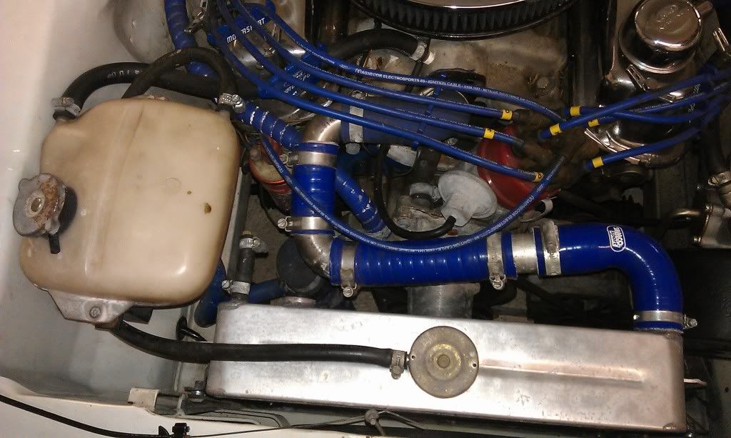
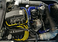
Looking at the photo, under the header tank you can see the blue hose that runs into the bottom of the header tank, and at the other end is connected into the lower rad - water pump hose via a T.Piece.
At the Rear and left of the header tank the hose runs into the block, on the block side of the thermostat.
At the rear and right, the hose runs into the neck of the radiator. The cap on the radiator has no pressure relief system, so the radiator and the header tank are connected at all times. The cap on the header tank has a pressure relief system built in.
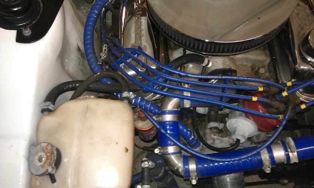
Close up of the header tank arrangement
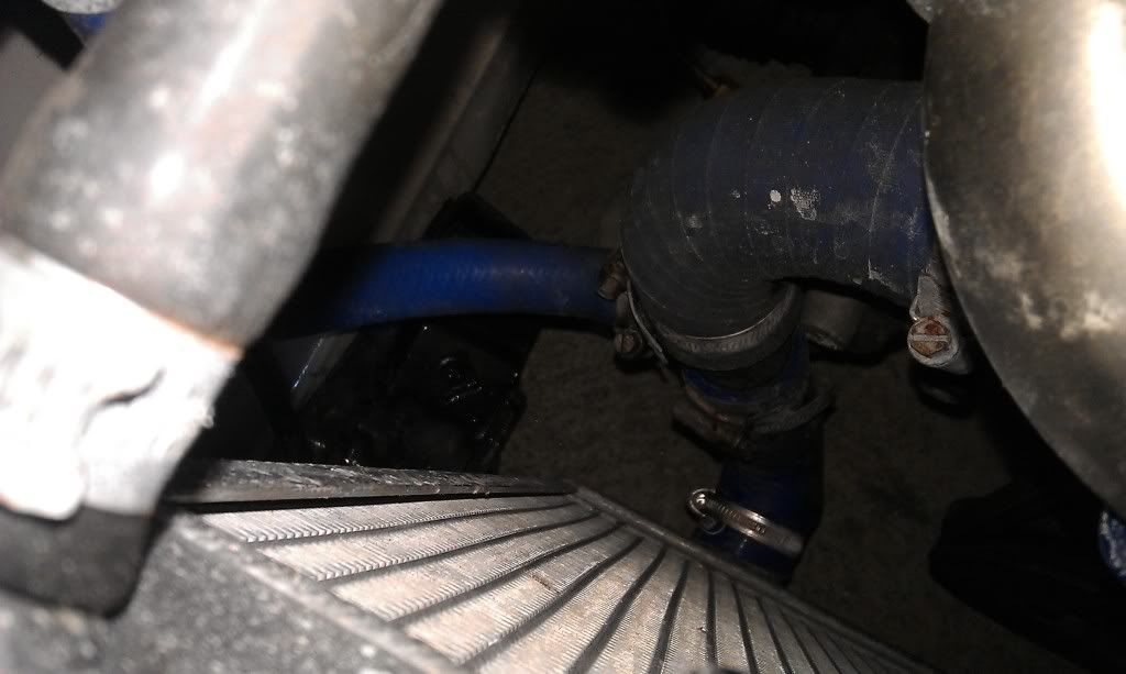
T-Piece into the lower rad hose
Does all this make sense?
Donald
Looking at the photo, under the header tank you can see the blue hose that runs into the bottom of the header tank, and at the other end is connected into the lower rad - water pump hose via a T.Piece.
At the Rear and left of the header tank the hose runs into the block, on the block side of the thermostat.
At the rear and right, the hose runs into the neck of the radiator. The cap on the radiator has no pressure relief system, so the radiator and the header tank are connected at all times. The cap on the header tank has a pressure relief system built in.
Close up of the header tank arrangement
T-Piece into the lower rad hose
Does all this make sense?
Donald
The fan is 12" diameter. It sits in front of the radiator and is set up the correct way, blowing air onto the radiator. It creates enough suction to keep a leaf pinned against the front grill when its on, but doesn't feel hugely powerful.Ian Anderson wrote:What sized fan?
And have you got it wired correctly?
No not joking is it sucking the air from in front and blowing towards the engine? Because if you have it the other way round it works well when stationary but works against normal air flow at normal speeds
Ian
-
Ian Anderson
- Forum Contributor
- Posts: 2396
- Joined: Sun Nov 19, 2006 9:46 pm
- Location: Edinburgh
12 inch fan is probably not man enough
It probably is rated at about 800 frm of free air
If you had a 16 inch one it wou
D be something like1600 CFM
I would think basically you are not moving enough air past the radiator to remove the heat
Kana
It probably is rated at about 800 frm of free air
If you had a 16 inch one it wou
D be something like1600 CFM
I would think basically you are not moving enough air past the radiator to remove the heat
Kana
Owner of an "On the Road" GT40 Replica by DAX powered by 3.9Hotwre Efi, worked over by DJ Motors. EFi Working but still does some kangaroo at low revs (Damn the speed limits) In to paint shop 18/03/08.
Hi Kana,Ian Anderson wrote:12 inch fan is probably not man enough
It probably is rated at about 800 frm of free air
If you had a 16 inch one it wou
D be something like1600 CFM
I would think basically you are not moving enough air past the radiator to remove the heat
Kana
I think you are probably right, and it will be something that I'll look at. I suspect that not enough cool air is getting in, and that the hot air under the bonnet can't escape. I'll also want to go to thermoswitch controlled fan, rather than a manually controlled - any thoughts on a supplier of a 16inch fan?
Before I do any of that though, I want to make sure its plumbed in properly, hence the original question. It probably is fine, it's just different from what I've seen before.
Donald
-
SimpleSimon
- Knows His Stuff
- Posts: 620
- Joined: Mon Apr 25, 2011 10:36 pm
- Location: East Sussex
I cant see any issues with that cooling system  in fact it mimick's the car it cam off of i.e 2.8i Capri/Granada except they have the stat in the bottom hose circuit rather than the top although I cant see that being a problem here
  both rad caps are in the right location too 1 blank rad & 2 expansion bottle pressurized cant comment on the rad or fan size as we cant see it properly.
Last edited by SimpleSimon on Mon Sep 03, 2012 1:02 pm, edited 1 time in total.
TVR Chimaera RV8 Mods & Megasquirt
Hi
does the rad completely fill the hole in the front panel? or there gaps at the side? My thoughts are that the rad is very thick cored it is going to be hard to get good flow through it, if there is any way air can bypass the core it will (it certainly looks as if air an come up over the top of the rad from in front between the rad and the front cross panel). My first priority would be to close any gaps around the rad.
As Eliot points out there are too many pipe joints and 90 degree turns you need to reduce the number of both.
Are you relying on the hole in the bottom of the engine bay to get the hot air out? if so I would consider putting some big vents in the bonnet to get some of he air out.
The Rover generally relies quite heavily of air flow around the lower part of the block and the sump for much of it's cooling get too much of it, like I did with a range rover that was lifted 3" over standard and I couldn't get the engine to heat up properly, i fixed it with a deflector in front of the sump, but you also hear of the reverse where owners put sump guards across the bottom of the RR and it over heats like mad.
Do you have a big aid dam across the front of the car? if so then try removing it.
Really what I think you need is a thinner section rad that takes up more of the width of the front of the car, I think if you opened up the front panel you could get another 3 to 4 inches of core width and probably have it so it does not extend so far down the front of the car and with the top tube entering the Rad on the side that matches where it comes out the rover engine. I also think a 12" fan is on the small side especially pushing through the core, you probably want a 16" fan. What is the shroud like? can the air just cycle around the fan blade tips?
I think you have lots of small areas reducing cooling efficiency a bit each, the trouble is you have so many, at least six or seven I can see, reducing efficiency by 5% to 15% each, they add up to a very inefficient cooling system.
Best regards
Mike
poppet valves rule!
