
My question concerns the bypass operation.
This is to me quite a brain teaser!
See my previous post on Manifold design.
I have been away from this site for some time, for that I apologise.
Great response last visit, find myself with a mind bending problem, needing your expert help.
Bare with me please in my long winded endeavours’ to explain.
Yes it could be said I am quite mad.
Try please to be constructive.
I have almost completed this project. (Waiting for the Bang)
In brief: 3.9 Rover v8, M90 charger. Sequential everything. Wolf v500. LPG and Petrol.
(I am only prepared to start on petrol initially.)
Have started but few issues to rectify
S ounds sweet in Garage standing still!
Currant Mods: Added separate crank and cam sensors removing VT distributor making room for home made air to air intercooler sandwich plate and outlets.
Zero decked the block . Rover now has squish. (Big risk) Comp probably 11.5 : 1 Possibly More.
Big risk yet again.
Grooved the heads after reading on net
Front mount 450 x 300 x 76 intercooler 75 mm pipes.
By the Way no one would deck the block without the pistons Removed,
So I squared it up and decked by hand. All is good with that.
Suck and see approach is very much out of caricature for me not normally a risk taker, just hoping to do better than the experts that designed the old girl.
When I fired it up, it sucked in the silicone on the temporary intercooler bypass pipe work, still was wafting for delivery of front mount cooler.
Rough tune, few Bangs, Retrieved pipewort from neibours house, running and got it to idle.
Thought all OK
Couldn’t restart
Decided to re think bypass area.
Here is my dilemma: Good luck understanding. On reflection I think I will introduce a drawing or pick.
Bit late hear in Aus.
You are welcome to ponder whilst I sleep.
This issue has been giving me curry and a head ace for some time.
Have a go all as I am very interested in all impute before Decision time. Crossing fingers so to speak.
1. I believe that the function of the bypass in the Eaton M 90 is to negate the pressure coming from the rotors and to redeliver it above them in the vacuum upstream of the throttle body butterfly.
2, I had two totally separate areas to the plenum beneath the charger.
One under the rotors and one under the bypass.
The one under the bypass is the feed, return cooled air that dumps into the top of a cut down SU manifold. It also serves the MAP sensor and air temp.
3. I am aware that at idle and low RPM the Pressurised air passes through the bypass butterfly to the intake of the charger downstream from the mostly closed throttle body butterfly to the vacuum area.
4, In my setup that air also spills into the inlet manifold when bypass open.
DONT KNOW IF THAT IS A PROBLEM.
CHOICES
1, Leave as is all ok (I didn’t observe wether the bypass was actually open when idling, vac line may have been wrong. I did also have an electrical problem hindering starting at the time.
2, Construct a chamber the same cross sectional area as the bypass venturi , install between the rotor plenum and the cooled return air plenum thereby bridging the separate areas and in doing so allowing some idle boost to be available to the intake manifold?
3, Should I also isolate that idle boost air from my return air area and intake manifold throat, thereby having a fully separate dedicated ducted air passage just for the bypass valve to serve beneath the rotors.
Peter From Aus.
3.9 Range Rover Supercharger manifold bypass question
Moderator: phpBB2 - Administrators
Thanks for the responses.
The throttle plate is before the charger.
I am hoping that grooving the heads will allow for higher compression ratio as is the claim on that indian fellas site.
Check out these picks especially the base plate album.
Hopefully they assist to explanation
my delema.
Please dont look too close to the welding Not finished yet
http://s1223.photobucket.com/albums/dd5 ... /BASEPLATE
Had a quick 'google' Sounds a bit fishy to me!!!I am hoping that grooving the heads will allow for higher compression ratio as is the claim on that indian fellas site.
It it was that easy to increase power/efficiency/etc... Then believe me all engine manufactures would be adding a simple little groove the their cylinder heads. I don't know of one?
Anyone else read about 'grooving cylinder heads'????
Tom.
Dax Rush 4.6 supercharged V8 MSII
Aha:Anyone else read about 'grooving cylinder heads'????
http://www.v8forum.co.uk/forum/viewtopi ... nder+heads
Dax Rush 4.6 supercharged V8 MSII
Thanks for posting the grooved head topic Dax.
You got the same info as me.
My rover motor had detonation at 8.25: 1 @28 degrees with charger no intercooler.
I believe that was mainly due to a squish of around 1.4mm to top of block plus the head gasket.
Zero decked now, good squish.
I will be monitoring the grove debate inform of my outcome (hope ok)
At present I am constructing aluminium ducting to cooler, still can’t decide on the bypass configuration.
Peter
Hi
What pistons are you using? just if they are not flat top, or "reverse crown" then any grooving of the heads in the region of the squish area is not going to do very much, I think the way this mod is suposed to work is to create a "jet" of charge moving toward the plug creating alot of turbulance and aid even burning, trouble is that the bpug has already lit off the mixture some 20 to 30 degrees before the piston is anywhere near enough the groove in the head for this to have any influance. A normal squish band is s differant matter as it is forcing unburnt mixture toward the flame front as the piston comes up.
What I am basically saying is that on petrol I think your setup will detonate like mad, stick it on LPG you should be OK if the charger is making less than about 6 psi at peak torque.
Are you sure you have 11.5:1 compression, because even with a decked block with standard dish rover pistons it is not easy to get much over 10.5:1.
Best regards
Mike
poppet valves rule!
Hi Mike, I do have the CR wrong
Motor was 8.25:1 surpentine 3.9.
Standard dish Pistons standard valves wich i throated out.
Head has not been plained.
Slight cam , have specs someware.
Need Help
When i calculate the CR of standard motor only get 7.67:1,
Figure i doing somthing wrong.
Could you please help to revise the ratio i would now have.
Now zero decked 40th head gasket providing the 40th squish.
I am chassing Volumeric Eficency turbulance.
stroke 71.12 mm
bore 94 mm
top of piston to deck was 1.4mm ( gone)
composit head gasket 1.2mm compressed
head chamber 27 cc
Thanks Mate
Hi
sorry about this but I'm going to need to know the volume of the dish on the piston, I don't know what the standard volume is, though someone on here will. I presume they are 36cc chamber heads (I think that is standard).
the equasion you want is CR= 1+ swept volume/ total volume above piston at TDC, so if you have zero decked the pistons it is dish volume + chamber volume + volume due to gasket thickness (I make gasket volume 7cc)
Sorry not to be more helpfull but I need the last two bits of info.
Best regards
Mike
poppet valves rule!
I'm only running 19 degree's of advance at 7psi on my new blower build.
Thats 19 degree's all in at 2500 rpm.
Thats 19 degree's all in at 2500 rpm.
Perry Stephenson
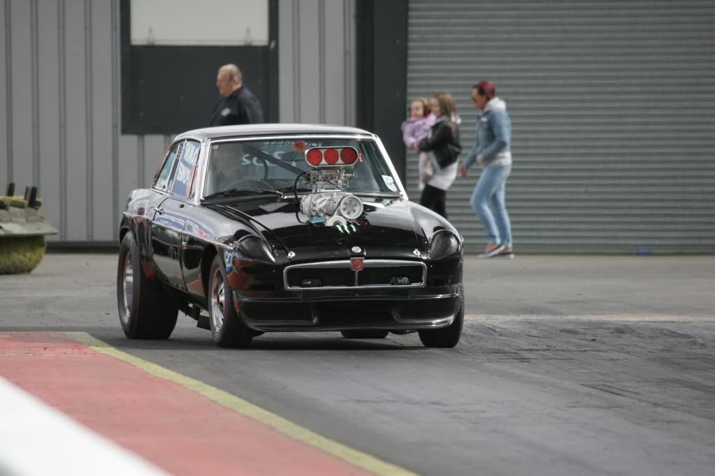
MGB GT + Rover V8
9.62 @ 137.37mph
Now looking for 8 seconds with a SBC engine
Thanks Mike
stroke = 71.12mm
Bore = 94mm
head chamber = 29.00 cc
deck to piston volume 9.71 cc 0 for o deck
piston dish volume 26.93 cc
head gasket = 8.27 cc
total 73.91 cc
3.9 stroke volume= 493.57
This is what i came up with for a standard 3.9
late model heads have 29cc chamber and thicker
head gasket to compensate
7.67:1 should have been 8.25:1
What have i done Wrong? have a go mate.
Peter
Hello Perry,
92 Range Rover with big wheels. Wolf v500 LPG/ PETROL
Thats intrested me, more info please.
Are you intercooled ?
I was running 25 deg at 2500 rpm no DET. Before fitting intercooler, decking, Grooving.
Not sure of CR.
Was standard 3.9 surpentine motor with tin head gaskets that leeked.
With our diferent weight and ratios, intrested to know your proformance figs.
Peter from AUS
Mine is a stock 4.6 with forged pistons and big wheels also. 30" tall to be exact.
No intercooler fitted due to space restrictions.
vehicle weighs in at 1300kg with me in it..
Edelbrock 800cfm carb and running a mallory distributor with msd ignition.
I dont have any way of tuning mine apart from looking at spark plugs, twisting the dissy and tweaking the carb. So I dont have any techy data.
On her first run yesterday she made 335hp with 468ft/llb at 19 degree's anf fuel looking almost perfect. Maybe a tad lean. But I can fit new jets in the carb
Perry Stephenson
MGB GT + Rover V8
9.62 @ 137.37mph
Now looking for 8 seconds with a SBC engine
