Page 1 of 1
SD1 Ignition Setup
Posted: Fri Aug 01, 2008 9:13 am
by simontwithers
Hi, I spent an hour or so last night reading all the posts that came up using the search on ballast resistors.
I understand how they work and that 12 volts is reduced to 9ish via the ballast resistor under normal running and that the full 12 volts is provided to the coil by bypassing the ballast resistor when the starter is cranking.
The standard sd1 coil then will be designed to run at a reduced voltage.
I know my SD1 engine previously ran a ballast resistor, however this is now changing vehicles again and i no longer have the ballast resistor or the low voltage coil. Is there any reason that i shouldn't just wire in the 12v coil i have without the ballast resistor circuitry. I am not using any of the sd1 loom so all of my wiring will be fresh.
The numbers from the Lucas dizzy are:
41673B
35DE8 1579
54420642
The dizzy is the "non" contact points type with the spining disc pickup and does have vacum advance.
am i missing any other parts??
Thanks in advance
regards Simon.
Posted: Fri Aug 01, 2008 10:12 am
by julian.jay
I avoided all of this by changing to an Aldon electronic unit. Very simple mod as it fits in place of the points. I also bought a new coil from them to be sure. I had a missfire before but this cured it and it even seems to sound better!!
Posted: Fri Aug 01, 2008 11:09 am
by ian.stewart
I dont think there will be any problem with doing this, but the RV8 electronics are notoriously unreliable in Hi heat applications, + a lot of them are using 30year old components, Aldon Ignitor or Pertronix, both the same thing, different lables, are well worth the effort., Rovers do respond well to having a Hi output coil, but seem to suffer with a Hi Rev Misfire if you have Hi comp and too wide a plug gap .
Posted: Fri Aug 01, 2008 12:03 pm
by simontwithers
I will be keeping the RV8 ignition to get me up and running, I can always upgrade later when my bank balance has recovered.
Can anyone confirm that the distributor will have no problems with a constant 12v coil supply.
Thanks again
Posted: Fri Aug 01, 2008 4:50 pm
by CastleMGBV8
Simon,
The information on RPI's site may be of assistance.
http://www.rpiv8.com/electrics-1.htm
Kevin.
Posted: Fri Aug 01, 2008 7:49 pm
by Pocket rocket
I can't see any reason wht the DE8 shouldn'twork with a 12V coil.
One of the reasons ballast resistors were introduced in the first place was to place less voltage across the points and thus reduce wear through arcing. The DE8 doesn't have points anyway...
Re: SD1 Ignition Setup
Posted: Sat Aug 02, 2008 5:38 am
by Paul B
simontwithers wrote:
I understand how they work and that 12 volts is reduced to 9ish via the ballast resistor under normal running and that the full 12 volts is provided to the coil by bypassing the ballast resistor when the starter is cranking.
That is pretty much the story; The coil is designed to run on, say, 9 volts when the engine is running normally, because that is about all it gets when the starter motor drags the current down whilst starting. The idea being the ballast is taken out of the system when you're cranking as the current drops and a normal 12 volt coil would be underpowered and not work so well.
It is a while since I did it and I can't remember the actual model of the dizzy setup, but my '84 SD1 had a 12 volt coil and the dizzy that comes with a separate little ally box of tricks, with the coil bolted to it. There was no ballast with that. I thought all SD1's were the same.
I eventually had the coil and the amp mounted inside the dashboard of the car and did away with the rest of the junk in the box of tricks, just used it to mount the coil and amp to.
Posted: Mon Aug 04, 2008 7:55 am
by ChrisJC
I am 95% sure that an ignition system with points will have a ballast resistor, and an electronic ignition system (i.e. no points, but a contactless pickup) will not have a ballast resistor.
This is because the electronic amplifier will compensate for battery voltage variation automatically.
I wonder if people sometimes mistakenly call the large silver box under the coil a ballast resistor when in reality it's an ignition amplifier.
Not sure about Opus though.
Chris.
Posted: Mon Aug 04, 2008 9:29 am
by simontwithers
with a 35DE8 should i have any 'silver boxes' to acompany my distributor or is everything internal ???
thanks.
ps - chris i notice your profile lists a v8 series 2a - this is what i am currently building.
Posted: Mon Aug 04, 2008 2:17 pm
by ChrisJC
According to Rimmer Bros
http://www.rimmerbros.co.uk/rimmer/rove ... e/ignition
The DE8 is Opus, and should have a ballast resistor.
Ballast resistors are external to the distributor.
Chris.
Posted: Mon Aug 04, 2008 2:24 pm
by Pocket rocket
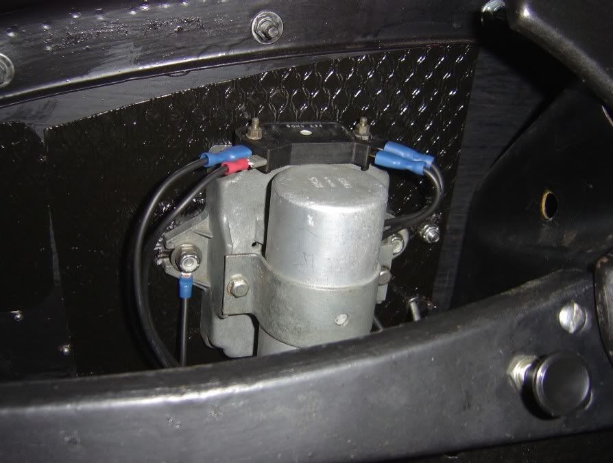
You need one of these

[/img]
and the connections are

[/img]
Posted: Mon Aug 04, 2008 9:01 pm
by simontwithers
thanks again, i will give it a go without the ballast resistor using my 12v coil. cheers
Simon
Posted: Sat Aug 09, 2008 5:43 am
by Robrover
I run an early Opus dissy fitted with a Lumenition optronic trigger, MSD 6A CD box and MSD Blaster 2 coil (12v with no ballast resistor), Eagle Spiral Core 9mm leads and NGK plugs. All seems to function ok.
Posted: Thu Oct 09, 2008 7:31 am
by satancom
Sorry to bring up an old thread. But I have an Opus dizzy and am going to be firing my engine up for the first time soon. I have stripped the connector off and connected it straight to a 12v coil rather than through the ballast resistor. It should work shouldn't it ?
White black to - and red black to + ? I also have a balasted coil knocking about, but don't really want the extrawiring for the ballast resistor!
Posted: Wed Oct 22, 2008 7:04 pm
by satancom
To answer my own question.. Yes it works with a 12v coil, red/black to positive, white to negative and 12v ignition live to coil +
