Page 1 of 4
today on bluepeter we're going to build... A Flowbench!
Posted: Fri Oct 19, 2007 9:07 pm
by HairbearTE
Here's another Hairbear abomination I thought I could share with you all. Due mainly to lack of funds after switching jobs this year I have put the Datsun on the backburner for a while and have spent most of this year rebuilding, re-wiring and leakproofing my workshop. I built an "L" shaped bench in one corner of my workshop and have integrated into it a fixture into which i'm going to build my flowbench. I'm going to build this bench to the best level I can whilst still trying to keeping costs reasonable. A new flowbench from superflow can cost £5K+ depending on which model and extras you have so let's see what can be done for a lot less.
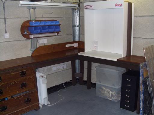
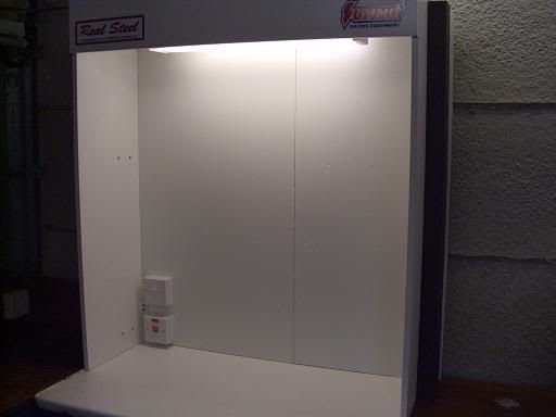
I have built a light into the fixture, and the red switch is an overide to switch the motors off.
I'll post my progress over the next few weeks (months more like). Any advice from you clever bods out there will be welcome.
Posted: Fri Oct 19, 2007 9:38 pm
by HairbearTE
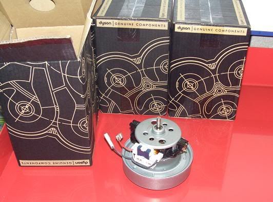
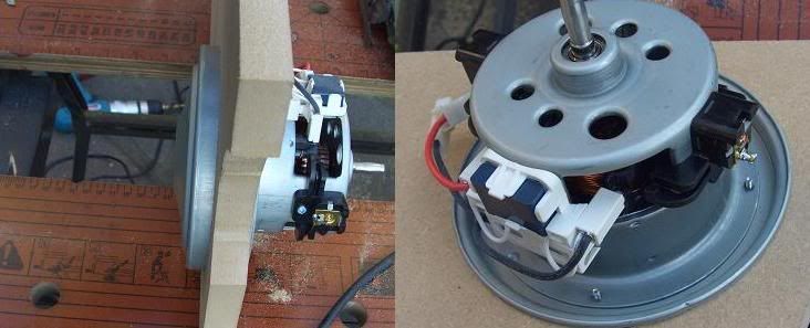
This will be the second incarnation of my flowbench, the first being a rather feeble affair in comparison. I had planned to source used motors for this project but I came accross this great deal on ebay. New genuine dyson motors for £16 each, so i've bought 4 of em! I'm going to try to find time to build the pump this weekend. Most of the wood I used to build the bench fixture I already had, although I did buy the narrow conti board that surounds the light fixing. Light, conti board, switches + wiring came to about £40 so £112 spent so far, not too bad. Here's the motors.
Posted: Fri Oct 19, 2007 10:27 pm
by Alley Kat
Interesting Marcus, keep the posts coming...
Posted: Mon Oct 22, 2007 12:44 am
by HairbearTE
Well I got a bit done today, but not as much as I'd hoped. As usual when building anything the time seems to be taken up more with measuring and mocking up than final assembly. Waking up at midday with a steaming hangover didn't help much either..
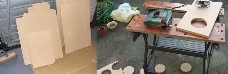
A trip to the local homebase yeilded a sheet of 18mm MDF for £23. Now I know homebase is not the cheapest for this kind of thing but they got a great cutting service there that I had to take advantage of. I planned out all my cuts on a piece of graph paper and got the guy there to cut it to my spec. First two cuts free, 50p each thereafter. I can't emphasise enough the grief you can save by using this service. If you haven't got at least a table saw at home then you just can't get close to these results. Total spend now £138.
Here I messed about with an offcut getting the circle just the right size for the motors. I wanted an slight interference fit to support the motors so after about 3 goes with the compass I got what I wanted, a hole just slightly too small that I could then finish off with a flap wheel. Better to fiddle around like this than cut a slightly too big hole in the work piece and have to junk it. As you can see i've left space in there for two more motors in the future if I decide that I need them. That would probably mean building a new box, but at least I know I could keep the same dimensions and thus keep upheavel to a minimum if I did go that route. I think four motors should be enough though.
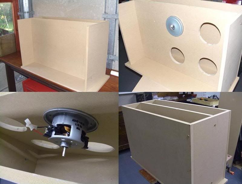
The precisely cut MDF went together first time dead snug, with no fettling required. Lovely. Anyone who's ever built a subwoofer box will be familiar with this kind of build. I've lined it all up and tacked it together with some screws here, in the week I shall glue it up and countersink all the screws for a nice finish and also cut a hole for the exhaust side of the box. The motors will be glued and sealed in firmly and smear of sealant around all the joins for added sealing before the lid goes on.
I am still debating the wiring of the motors and the current plan is to wire them in two pairs, with one pair on a delay starter. The circuit should be well up to this but the motors are rated at 1400w each so best to be on the safe side. Anyone out there who would like to comment on the wiring for these? I would welcome suggestions, for example would it be possible to wire each pair of motors in series? would there be any point in doing so?
Hope to finish the pump this week, will post any progress
Posted: Mon Oct 22, 2007 8:09 am
by Eliot
Difficult to see from the photos, but i assume the actual fan is inside the housing?
Posted: Mon Oct 22, 2007 11:52 am
by bill shurvinton
They be dyson motors, so you need to add the fan (or in the case of a dyson the cyclonic dodad).
I must admit to having a folder at home with ever set of DIY flowbench plans ever posted on the internet for when I finally get a round tuit.
Posted: Mon Oct 22, 2007 6:34 pm
by HairbearTE
Eliot yes the fan is inside the housing. I must admit to being slightly skeptical as the the fan is not very big, Bills comments do not bode well for the dyson motors either since there is no room in my pump for cyclonic dodads! I shall fire up one of the motors and make an assessment before I go anywhere near it with the wood glue..
Bill I have a few such plans from books and the net but I am not sticking to them rigidly, rather I have taken a few cues from here and there to suit. Feel free to email me anything you feel may be useful to me for this project, including suggestions for alternative motors should these turn out to be pants! I was looking at the Ametek motors but they weren't turning up second hand and the new ones were much more expensive, when these came along at £16 each new I thought I'd give 'em a go.
Posted: Mon Oct 22, 2007 7:05 pm
by Eliot
big old truck turbo and a great big motor + step up gearbox?
Posted: Mon Oct 22, 2007 8:50 pm
by HairbearTE
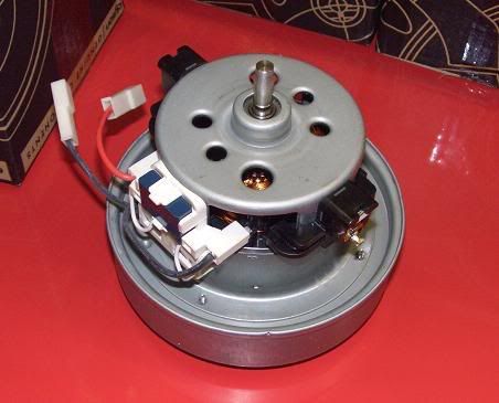
Right, just tested the motor. Carefully mocked up in the test rig (ie sat on my black & decker workbench) and skillfully wired (speaker cable straight into a plug, no earth) I gingerly switched the mains switch with the help of a broom handle from just outside the workshop. Nothing went bang but I've got to say the noise the thing kicks out is astonishing, sounded like a little jet engine. Once I was satisfied that it was operating safely I carefully put my hand underneath it and it nearly had it off! There is no way that 4 of these beasties is not going to be enough. A small bench could be made with two of these. Although the test showed the motors will be fine it has raised the issue of noise pollution. Obviously once the motors are in the box the sound will be muffled but I may have to perhaps insulate the box and lag the pipes etc. when it's finished.
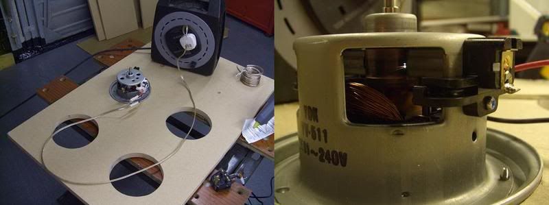
Here's the 'test rig' and in the second shot motor is running, you can just see spark in photo.
Posted: Mon Oct 22, 2007 9:21 pm
by bill shurvinton
Having chatted with a friend who used to work for dyson I think I may have been wrong. You could be OK with that. Only one way to find out

You seem to be on the right path. I would have each motor individually switched myself, to give you a better range of flows to work with.
Get your orifices calibrated on a superflow is always good, unless you want to have all your flows measured in dooburies rather than CFM.
If it were me I would use MAP sensors and a computer rather than manometers, but YMMV and you might like the old tech, at least until you have slurped all the water out them for the 10th time by mistake
Posted: Tue Oct 23, 2007 4:10 pm
by ihatesissycars
Get your orifices calibrated
He hee hee

Posted: Sat Oct 27, 2007 11:57 am
by Wotland
Hello Marcus,
Very interesting.
I have try myself to make one flowbench with informations aviaible in Burgess and Gollan Cylinder heads book.... but without success...

Posted: Sat Oct 27, 2007 8:47 pm
by scarecrow
dose this mean we`ll all be throwing datsun/dyson/ mdf contraptions down the strip in the future or have i got the wrong end of the stick?
Posted: Sun Nov 11, 2007 11:37 pm
by HairbearTE
At last I got a bit more done with the flowbench today, have been messing around building a welding table for the last week or so but am now back on track. The air pump shown in the previous pictures is almost finished now, I have made a trap-door style exhaust vent that I can open when using the bench but will keep spiders out while the bench is not in use.
Started on the orifice chamber today. I am not building this bench in a "cabinet style" so the major components are all seperate and linked together with pipes as opposed to being all contained within chambers in one box. There are various advantages and drawbacks with both methods but having all the components seperate does allow for future upgrades and allows for things to be moved around and changed if needed etc. I wanted to be able to change orifice size so a simple oriface within a welded up drum wouldn't do (unless I wanted to keep a selection of different orifice drums and swap them around as needed - no thanks). Finding a solution to this was made easier when I found some useful pieces of pipe leftover by workmen laying new gas pipes locally.
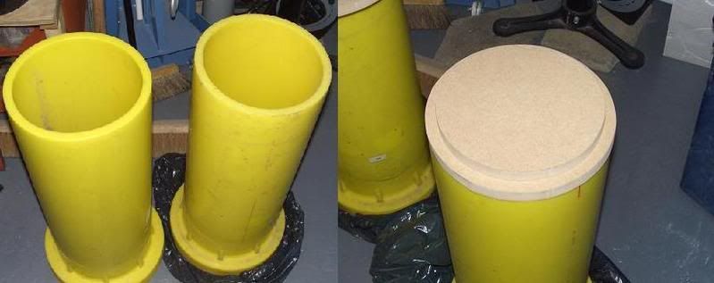
Amongst the many useful bits were some flanged sections that I figured would come in handy and so it has proved. The plan is to drill the flanges so that the two sections can be bolted firmly together sandwiching an orifaice plate, some 1mm rubber sheet can be cut to make gaskets for either side. Firstly I had to cut down the pipes as they were both far too long for my needs and this I did with the trusty jigsaw, but what a pain. This stuff is unpleasant to cut. After barely an inch of blade travel the blade is clogged up with a plastic wool that completely blocks the line of sight. Anyway, once trimmed to length I set about making some end plugs out of MDF. A quick measure of the pipe and then 5mins with the jigsaw and I had two nice round plugs for the pipe ends. Upon fitting them up I discovered the pipe wasn't quite as round as it could have been so rather than relying solely on big gobs of glue and silicone to seal it up I decide to make up two more plugs, this time the same diameter as the O.D. of the pipe. The two plugs will now be glued and screwed together to form a proper plug that can be fixed securely to the pipe ends.
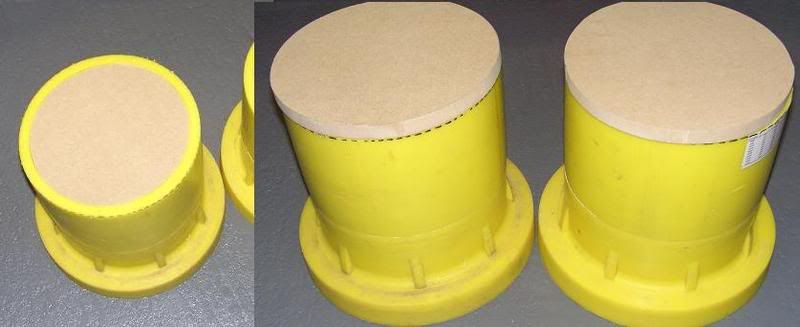
Here you can see the end plugs made from MDF.
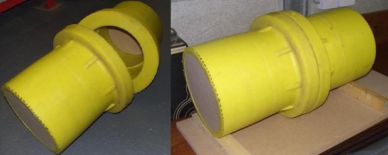
From these pics you can see where the chamber will bolt together allowing different orifice plates to be used. The pipes cost nowt and the MDF was offcuts from that used to build the pump. I did spend £2 on some rubber feet for the pump though, total spend on project now £140.
Posted: Tue Nov 13, 2007 9:05 pm
by DrDeAtH
its gonna be another monster........