Page 1 of 2
Cam position sensor
Posted: Mon Apr 15, 2013 9:02 am
by DaveEFI
I'm going to change my Megasquirt2 to a 3, and am considering going sequential on my SD1. I'd guess most who do this will use the later V8 with cam sensor - can this be fitted to the SD1 front cover? I could obviously use a modified dizzy - but that would a large lump. Or is there one which could be adapted to use the dizzy drive?
Posted: Mon Apr 15, 2013 6:29 pm
by ChrisJC
I guess if you use the appropriate cam-gear, then I don't see why you couldn't modify the front cover accordingly. But it might be easier just to change the front cover (and sump) for the later one with the hole for it.
Chris.
Posted: Mon Apr 15, 2013 10:38 pm
by DaveEFI
IIRC, the snag is the water pump is mounted lower down the engine than the RR. Because of the lower bonnet line.
Has anyone got a pic of the cam wheel - and could it be used with the SDI set up given the oil pump arangments? Can't imagine it would be too much trouble to fit a sensor to the cover.
Posted: Tue Apr 16, 2013 8:40 am
by DEVONMAN
DaveEFI wrote:IIRC, the snag is the water pump is mounted lower down the engine than the RR. Because of the lower bonnet line.
Has anyone got a pic of the cam wheel - and could it be used with the SDI set up given the oil pump arangments? Can't imagine it would be too much trouble to fit a sensor to the cover.
Hi Dave,
The later RV8 front covers have the water pump pretty much in the same position as the SD1 but the pump runs anticlockwise. Unless you want to rearrange the belt and change to multi-v it a bit of a task.
The later cam wheels that have the sensor facility will not fit the cam from a dizzy engine as they bolt to the end of the cam and don't slide onto it like the SD1 type.
Maybe you could put a larger washer at the front of your existing cam and somehow incorporate a cam sensor notch into it with the pickup through the cover. It probably doesn't need to be super accurate as it's only detecting that No1 is close to firing.
Just a suggestion off the bat. Maybe the water pump gets in the way.
Not much help I know.
Regards Denis
Posted: Tue Apr 16, 2013 8:51 am
by DaveEFI
Thanks guys. Seems the easiest way would be to use a modified dizzy.
Posted: Tue Apr 16, 2013 11:59 am
by DEVONMAN
DaveEFI wrote:Thanks guys. Seems the easiest way would be to use a modified dizzy.
I remember seeing a cam sensor inductive pick up from plug lead No1 but I can't remember where. Same principle as a timing gun but with a modified suitable output to the ecu.
You seem to be good with electronics so maybe there's a little project you could develop.
Regards
Denis
Posted: Tue Apr 16, 2013 12:18 pm
by DEVONMAN
Just realised the plug lead pick up idea will not work if you are using wasted spark due to the wasted pulse for No 6.
Posted: Tue Apr 16, 2013 4:54 pm
by ChrisJC
As Denis says, the fan position on the P38 Range Rover engine is pretty much in the same place as on the SD1. It's much lower than on the older Range Rover front covers.
It would be a fun project to fit the front cover + sump + ancillaries from a P38 engine.
Chris.
Posted: Tue Apr 16, 2013 10:40 pm
by DaveEFI
ChrisJC wrote:As Denis says, the fan position on the P38 Range Rover engine is pretty much in the same place as on the SD1. It's much lower than on the older Range Rover front covers.
It would be a fun project to fit the front cover + sump + ancillaries from a P38 engine.
Chris.
That's good to know. But IMHO the cost of doing all that rather outweighs any advantages.
Posted: Fri Apr 19, 2013 10:51 pm
by dnb
I too am looking at this problem. I have an intermediate Serp timing cover that I've drilled & tapped for a Honeywell hall sensor (the boss is cast in, so it's easy) however the sensor is too short to reach the pulley, and if I fit a disc, it will intersect with the casting where the dizzy is supposed to fit. I can't replace the dizzy because I used that space for something else...
I think the Range Rover sensor is longer, so this might help. Does anyone have measurements?
Posted: Fri Apr 19, 2013 11:21 pm
by DaveEFI
What sort of length of sensor do you need? I have one which is cylindrical, 47mm long, and threaded for 36mm of that.
Posted: Fri Apr 19, 2013 11:31 pm
by dnb
This is the sensor I have:
http://uk.rs-online.com/web/p/magnetic-pickups/2355706/
It's 31.8mm long and 17.9mm in diameter and fits precisely in the OEM boss other than being apparently too short. I haven't got the measurement to hand at the moment but 47 might be a bit long. I can measure it over the weekend.
Posted: Sat Apr 20, 2013 7:53 am
by DaveEFI
The one I have is threaded along the body, so would either screw into the housing or be held by a couple of nuts. It's this one:-
http://www.diyautotune.com/catalog/hall ... p-489.html
Posted: Sat Apr 20, 2013 9:32 am
by stevieturbo
Some pictures on google...one shows the OEM cam sensor location.
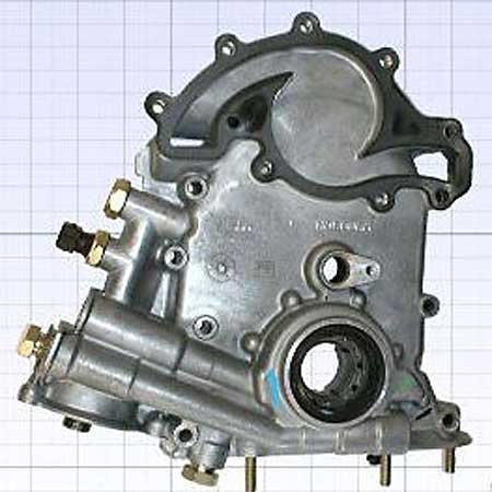

Can an older cover just have a boss welded on and drilled/tapped and use the threaded type sensor to sort distance ?
Then just weld/braze a small single tooth onto the camgear ?
Posted: Sat Apr 20, 2013 5:02 pm
by dnb
Both of those pictures show the OEM cam sensor location. One is drilled to accept the sensor, and the other is not.
I can't see any reason why it wouldn't work to add a tooth to a cam wheel. The only constraint is that it would need to get past the casting where the dizzy fits. This is quite big IIRC.
These are the various cam wheels available:
http://www.v8wizard.com/Camshaft_timing_chains.php
I have a JP set, so it appears I will struggle to get a single tooth in a sensible place on the wheel.