Page 1 of 2
Coolant path around the engine
Posted: Sat Sep 22, 2012 7:49 am
by Discopotatoes
Hi all
Can some one explain the route the coolant takes when it gets to the pump?
The reason for the question is, I have my return feed from the heater plumbed in to the off side part of the water pump housing where there is a hole going into the block, and I have no heat from the heater, this is a new install and since getting it back the heater hasn't worked.
As there are two holes i thought it might be a flow and return?
I hope I have explained myself clearly,
Many thanks
Posted: Sat Sep 22, 2012 9:22 am
by Darkspeed
All ports on the pump are returns
Flows are off the inlet manifold
Plenty of posts and explanations on the subject if you do a search
Posted: Sat Sep 22, 2012 11:34 am
by Discopotatoes
Darkspeed wrote:All ports on the pump are returns
Flows are off the inlet manifold
Plenty of posts and explanations on the subject if you do a search
Thanks,
I have spent hours searching this forum and others, non of them seemed to answer my question properly,
If the pump is pumping into the block into both holes would it not therefore pump back up the said heater return pipe ( which might I add was originally plumbed into the radiator side of the pump)
Just to be clear its the holes in the block where the pump is bolted to that I'm refuring to.
Posted: Sat Sep 22, 2012 10:01 pm
by stevieturbo
Water flows from the pump...to the rear of the block. Then up into the heads and back out the front into the rad via the stat.
Posted: Sat Sep 22, 2012 10:17 pm
by Discopotatoes
stevieturbo wrote:Water flows from the pump...to the rear of the block. Then up into the heads and back out the front into the rad via the stat.
I'm not getting far with this!
With the water pump removed there are two holes in the front cover, does the pump, pump coolant equally into both holes or is one a flow and the other a return? As my heater return pipe is plumbed into the part of the water pump housing that goes directly into the driver side hole. It was move from its previous location which was on the inlet / radiator side of the pump
Posted: Sun Sep 23, 2012 7:43 am
by stevieturbo
I explained in the most simple way I can possibly think of.
Dont quite get how you dont understand ? Post a picture of the block or what you dont get ?
Posted: Sun Sep 23, 2012 12:12 pm
by ramon alban
Assuming you are talking about a standard Rover V8 system then, have a butchers at the PDF available from this link
http://www.vintagemodelairplane.com/pag ... ing01.html
and you will find there are actually two circuits involved.
The first is before the thermostat opens and the second is after it opens, bringing the radiator into play.
The same PDF will teach you everything you need to know how the typical bog standard RV8 cooling system works, how to analyse faults and how to fix them!
Posted: Sun Sep 23, 2012 1:54 pm
by ChrisJC
Discopotatoes wrote:stevieturbo wrote:Water flows from the pump...to the rear of the block. Then up into the heads and back out the front into the rad via the stat.
I'm not getting far with this!
With the water pump removed there are two holes in the front cover, does the pump, pump coolant equally into both holes or is one a flow and the other a return? As my heater return pipe is plumbed into the part of the water pump housing that goes directly into the driver side hole. It was move from its previous location which was on the inlet / radiator side of the pump
They are both returns.
One is from the heater. The other is the thermostat bypass which is a short pipe running from the inlet manifold next to the thermostat to the rear of the water pump.
On some front covers, one of those two holes is plugged. If you are 'mixing and matching' parts, then you need to be sure that the used ports are open......
Chris.
Posted: Sun Sep 23, 2012 2:47 pm
by Discopotatoes
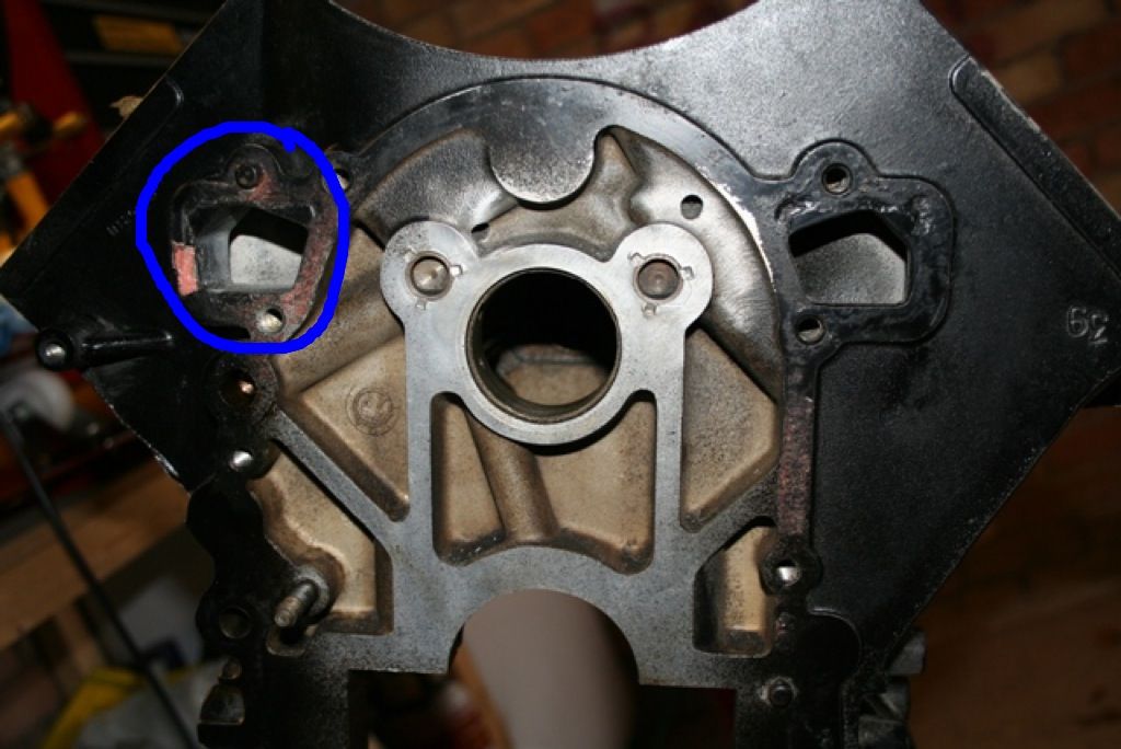
This is the hole I'm trying to describe, the return from the heater matrix goes directly into here.
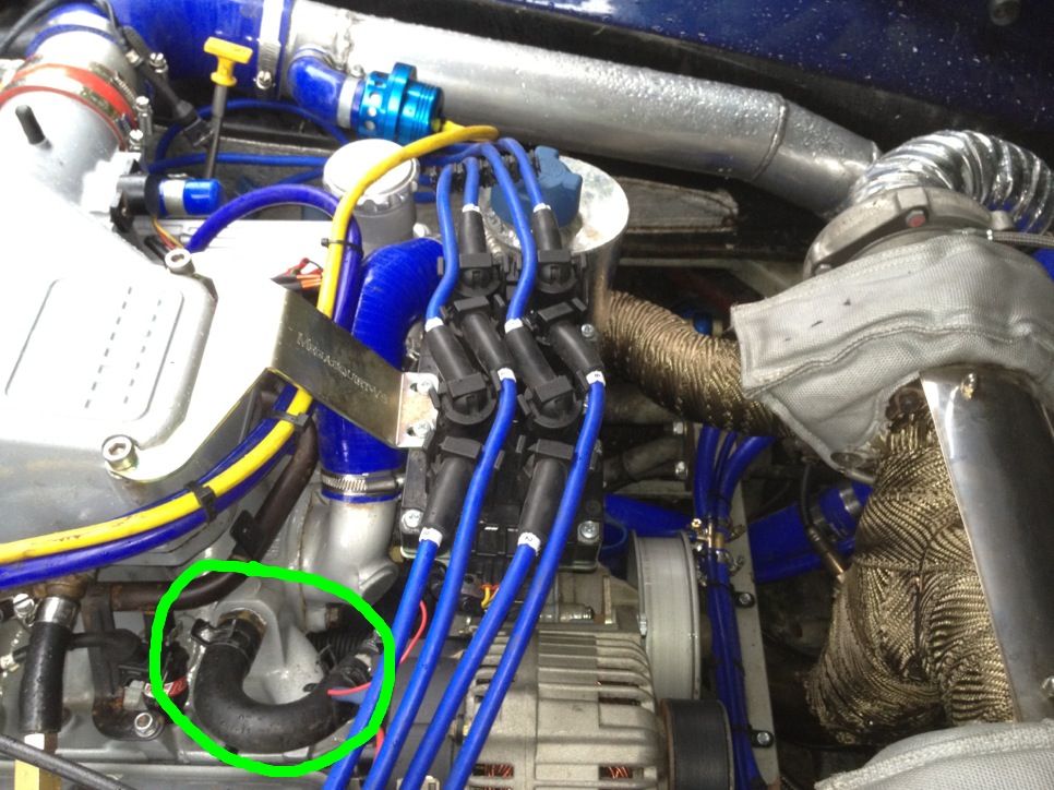
And this is the feed to the matrix
Posted: Sun Sep 23, 2012 3:58 pm
by ChrisJC
Lower picture - correct. That is the feed to the heater matrix. You appear to have a late front cover, so presumably there's a multiple-ported thermostat in the bottom hose? Or if not, where does the heater return to?
The top picture - both the holes are where the water pump feeds the water into the block. They are fed from the water pump / front cover assembly. I don't understand how you say that the heater return goes in there as they are covered up by the front cover?
, the return should
Chris.
Posted: Sun Sep 23, 2012 4:52 pm
by Discopotatoes
It is an intermediate front cover, the pump housing has been drilled and tapped in the area of the blue circle and the return pipe from the matrix is plumbed into it.
I have now got an answer from another forum, and as expected its in the wrong place, looks like I will be changing it to the other side of the pump this week
Thanks for all your help guys
Posted: Sun Sep 23, 2012 5:30 pm
by stevieturbo
Heater return really needs to go back into the system before the water pump. The pump usually has a pipe for this though.
Heater supply can be anywhere between the water pump and thermostat
Posted: Sun Sep 23, 2012 6:13 pm
by ChrisJC
Discopotatoes wrote:It is an intermediate front cover, the pump housing has been drilled and tapped in the area of the blue circle and the return pipe from the matrix is plumbed into it.
Bizarre!
Chris.
Posted: Sun Sep 23, 2012 6:38 pm
by Discopotatoes
ChrisJC wrote:Discopotatoes wrote:It is an intermediate front cover, the pump housing has been drilled and tapped in the area of the blue circle and the return pipe from the matrix is plumbed into it.
Bizarre!
Chris.
Yep and obviously very wrong!
It's a 4.6 cross bolted block bored to 96mm with my original intermediate front cover from my 4ltr Tvr lump, so the dizzy is now redundant and has had the hole capped off with a bung,
I really have no idea why that location was used for the return feed as it was in the lower inlet pipe on the pump to start with
Posted: Thu Sep 27, 2012 5:56 am
by Discopotatoes
Quick update:
After pulling the stat I found a large airlock in the inlet manifold, fitted another new stat 82deg topped it up,now the heater works a treat so that pipe was ok in it's current location, sorted out a bit of dodgy wiring and the coolant system settles at 85deg. Happy days!