Hotwire ECU Goosed?
Posted: Sun Apr 01, 2012 8:28 pm
Hi All
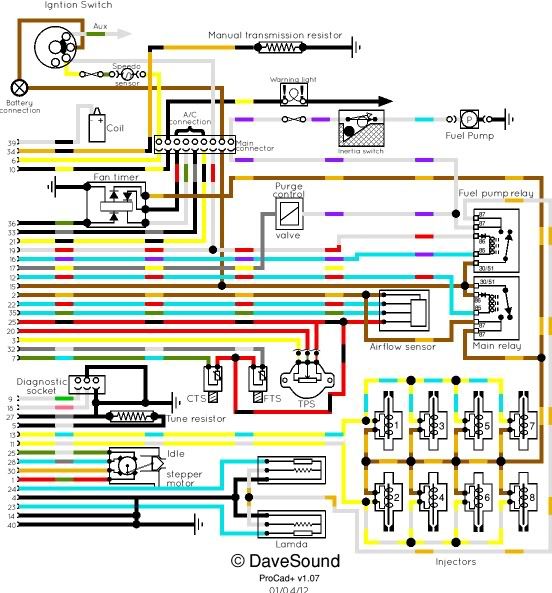
In the final throws of fitting Hotwire to my 90, thought today I'd get it running before finishing off, and no surprise's no start , not even a quick blast from fuel pump, so I am wondering if the ECU is goosed, everything is wired up as per advised on here;
Brown to permanent live feed
White to Ignition 'on' live
White/Purple to fuel pump
With regard to the White wire, it is connected to the White/Red on the EFI loom as there wasn't a white wire, and it appears the White/Red goes to Fuel pump relay so I assume this is correct?
I have live (battery voltage) to all the fuel pump relay terminals except for the White/Purple with the ignition on - is this correct?
There is no relay in the Air-con fan relay base (I assume this doesn't matter)
There is a resistor fitted to the loom as per posts to tell it that there are no Lambda's, although the loom has Lambda connectors - i.e it's off of a @ '92 vehicle which would have had lambda's fitted - do I need to fit anything into those plugs for it to work?
The ECU is from a @ 92 3.9 with Lamda's.
I bought the whole lot off of a guy on Ebay, so no gaurauntee's the ECU or any of it for that matter was working before, unfortunately I don't have a spare one to try.
Greatful for any help/advise where/what to check, have I missed something obvious?
Thank in advance
Regards
Mark