Page 6 of 9
Posted: Fri Jan 29, 2010 7:41 pm
by Darkspeed
Posted: Fri Jan 29, 2010 7:57 pm
by sidecar
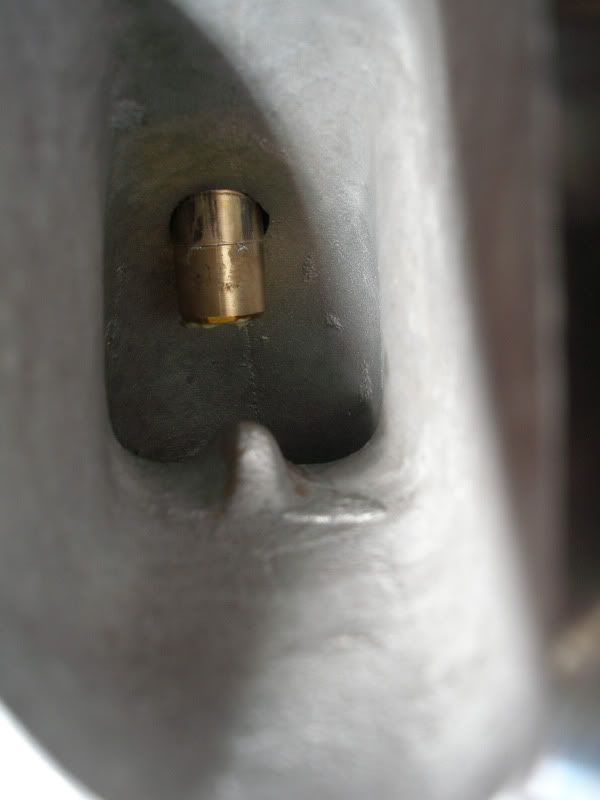
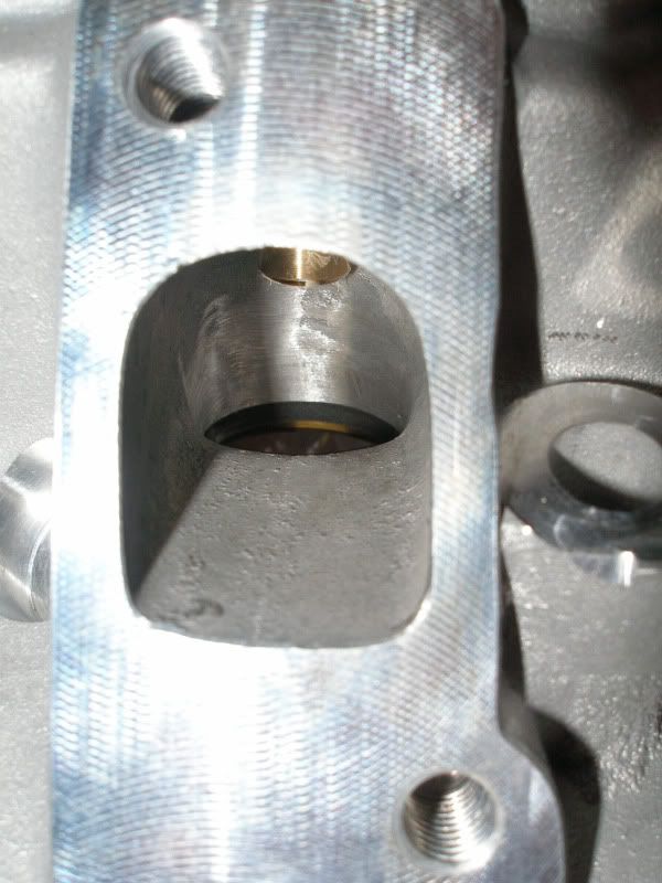
Just a thought but the way that the lump in the inlet track lines up with the valve stem makes me think that it's there to create some sort of divider to split the inlet charge before it hits the valve stem. I can't believe that it makes much difference though! (And I could be totally wrong anyway!)
Posted: Fri Jan 29, 2010 8:00 pm
by Speed 8
OMG this thread already has my vote for thread of the year. This is excellent stuff guys!

Can't believe his headness Mr. Burgess joined the discussion, just bought his book 2 weeks ago!
Posted: Fri Jan 29, 2010 8:16 pm
by burgesstuning
Hi Dave
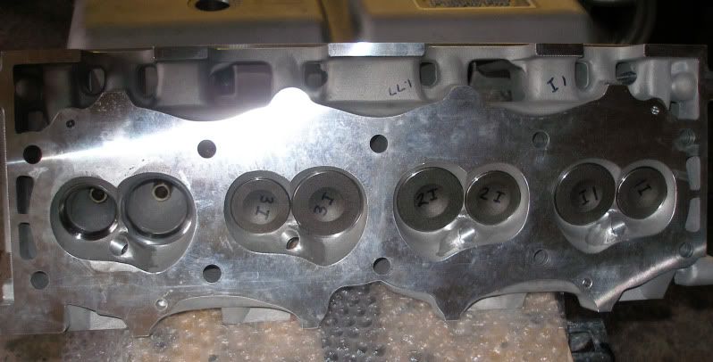
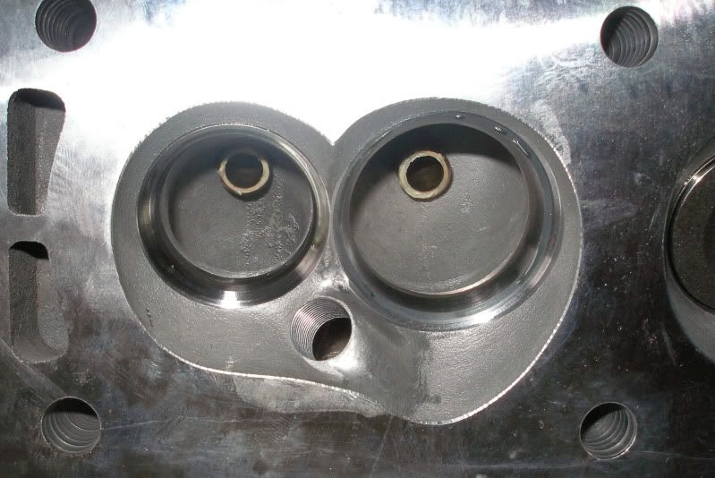
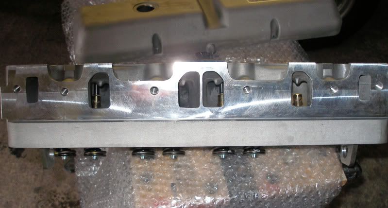
Looks poor doesn't it? We get some MGB heads from the US that need mega work to make em flow well. The Merlin heads seem unshrouded a little too much opposite the short side, not good for combustion, may cause prem detonation. It would be interesting to see a pair in the flesh. I cannot see why it needs the aerofoil thing-of-purpose?
Hi Speed 8, I hope you enjoy the book. If you ever make it to my unit I will sign it for you with pleasure.
Peter
Posted: Fri Jan 29, 2010 11:59 pm
by bigaldart
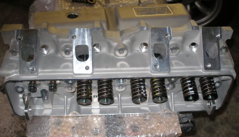
I am interested in the exhaust port and it looks like a little work in the bowl area and raising the port roof a little would make a huge difference. I am not sure of the purpose of the vane but remember reading something a lot of years and even more pints ago. Will have to find the references again I suppose. I still think they are a screaming deal and seat of the pants feel on a road car will be better than any stage 3 or 4 modified Rover head. I do think with the little bl;ower cam in the dragster they will make a huge difference, just a shame they are not a straight bolt on. We would need new head studs so swapping for back to back runs is tricky, also RS don't have a stud kit yet.
Alan
Posted: Sat Jan 30, 2010 12:02 am
by bigaldart
On another look the inlet port shown in close up looks different to the rest, is this just the picture angle?
Alan
4 bottles of Old Speckled Hen later
Posted: Sat Jan 30, 2010 6:48 am
by burgesstuning
Hi Dave
I have been pondering the criticism of my flow bench since you told me about it yesterday, always interesting when someone states 'categorically' that something is wrong and has a design flaw!
I developed my flow bench to measure air flow in a repeatable manner so accuracy of readings and end results were most important, I have never stated the figures are accurate as measured by a 'micrometer' in fact if we get into fractal maths how can we measure how long a piece of string is? My flow bench compares two pressure drops one of which is across an orifice of known size and approx 59.6% efficiency, with measurements of the pressure drops,temp,humidity and atmospheric pressure we can calculate airflow. Now my bench does not need to be calibrated on a daily basis as my maths calculates the effects of atmospheric changes. We are dealing with a process where everything apart from entropy changes, hence isentropic process. An item that flows x cfm on my bench at 25" H2O will always flow X cfm @25". I do not set bench to 25" H2O I calculate what flow would be at 25" H2O.
Now along comes someone that gets different figures from mine, their assumption is that my bench is wrong and to 'prove' it they say I am measuring pressure drop accross the head at a point of recovery. If you stop and think about it...if I increase the pressure drop accross the head my final figure will be alower one. I put the following figures in...T =15, Atmospheric pressure 1013.25mb, vapour pressure 1400n/m2, humidity T 0.80, valve 41. For first calculation assume pressure drop across head 1400mm H20 and pressure drop across orifice is 350 mm. Flow at 25" H2O is 46.06 cfm.
Now increase pressure drop across head (cos the 'experts say this is the case because I have tapped it wrong and the drop across the head should be higher) to 1500 mm H2O , keep all other figures same and you get a new cfm of 44.24 which is lower still. It shows that the 'experts' do not follow how my bench works and maybe, just maybe, they are wanting to find fault with my bench per se!
As I said I set out to build a bench to give excellent repeatability. The numbers are irrelevant as each flow bench operator must learn their art from their own figures. The mods I outline in my book work, they are not bullshit guessed at but produce real bhp gains. The heads can always be improved more but we are into diminishing returns.
I know I have rambled on but I feel I wanted to counter the criticism of my bench. Now maybe my bench does read 20% low, it doesn't matter. But if the figures are low it isn't due to a pressure recovery in my bench, that would make my figures even lower and that would never do would it?

Over the years we have flow tested a lot of heads that have been on different flow benches. All the figures have been different on my bench (apart from the 'calibration' holes we tried in conjunction with the Harry Weslake flow bench). Most of the heads had been on different superflow benches and the figures were different from different benches. I am not bothered what the figures actually are, as long as you supply your customer with a product that works that is what is required. I have seen heads flowing (according to the certificate...)way more than a standard head only flow about the same as a standard head on our bench, did the person who originally rework the head sell flow figures or performance gains?
ramble ramble
Peter
Posted: Sat Jan 30, 2010 8:23 am
by Darkspeed
Hello Peter,
It's Andrew by the way
Your explanation is appreciated and welcomed and the fact that someone as experienced as yourself is taking the time to converse through this somewhat difficult medium of the internet message board is really pleasing - Hopefully in the near future I will drop by your unit get my book signed, buy a couple of porting burrs and sundries and if there's a good local nearby buy you a pie and pint to compensate.
I ran the figures on the Merlins through the calc sheets I am putting together and from what notes I have the Merlin throat diameter was 39.5mm on a 45mm Valve.
From what my spreadsheets are throwing out it flows with 70% efficiency
Graph representation below
As it has been produced rather hastily and I am still learning as I go along with this I am yet to appreciate fully what its telling me ....that is if its at all accurate.
so pinch of salt with this one at the moment
Andrew
Re: 4 bottles of Old Speckled Hen later
Posted: Sat Jan 30, 2010 9:11 am
by sidecar
burgesstuning wrote:Hi Dave
I have been pondering the criticism of my flow bench since you told me about it yesterday, always interesting when someone states 'categorically' that something is wrong and has a design flaw!
I developed my flow bench to measure air flow in a repeatable manner so accuracy of readings and end results were most important, I have never stated the figures are accurate as measured by a 'micrometer' in fact if we get into fractal maths how can we measure how long a piece of string is? My flow bench compares two pressure drops one of which is across an orifice of known size and approx 59.6% efficiency, with measurements of the pressure drops,temp,humidity and atmospheric pressure we can calculate airflow. Now my bench does not need to be calibrated on a daily basis as my maths calculates the effects of atmospheric changes. We are dealing with a process where everything apart from entropy changes, hence isentropic process. An item that flows x cfm on my bench at 25" H2O will always flow X cfm @25". I do not set bench to 25" H2O I calculate what flow would be at 25" H2O.
Now along comes someone that gets different figures from mine, their assumption is that my bench is wrong and to 'prove' it they say I am measuring pressure drop accross the head at a point of recovery. If you stop and think about it...if I increase the pressure drop accross the head my final figure will be alower one. I put the following figures in...T =15, Atmospheric pressure 1013.25mb, vapour pressure 1400n/m2, humidity T 0.80, valve 41. For first calculation assume pressure drop across head 1400mm H20 and pressure drop across orifice is 350 mm. Flow at 25" H2O is 46.06 cfm.
Now increase pressure drop across head (cos the 'experts say this is the case because I have tapped it wrong and the drop across the head should be higher) to 1500 mm H2O , keep all other figures same and you get a new cfm of 44.24 which is lower still. It shows that the 'experts' do not follow how my bench works and maybe, just maybe, they are wanting to find fault with my bench per se!
As I said I set out to build a bench to give excellent repeatability. The numbers are irrelevant as each flow bench operator must learn their art from their own figures. The mods I outline in my book work, they are not bullshit guessed at but produce real bhp gains. The heads can always be improved more but we are into diminishing returns.
I know I have rambled on but I feel I wanted to counter the criticism of my bench. Now maybe my bench does read 20% low, it doesn't matter. But if the figures are low it isn't due to a pressure recovery in my bench, that would make my figures even lower and that would never do would it?
Over the years we have flow tested a lot of heads that have been on different flow benches. All the figures have been different on my bench (apart from the 'calibration' holes we tried in conjunction with the Harry Weslake flow bench). Most of the heads had been on different superflow benches and the figures were different from different benches. I am not bothered what the figures actually are, as long as you supply your customer with a product that works that is what is required. I have seen heads flowing (according to the certificate...)way more than a standard head only flow about the same as a standard head on our bench, did the person who originally rework the head sell flow figures or performance gains?
ramble ramble
Peter
I'm sort of dipping in and out of this thread but whoever is moaning about your flow bench does not know their ar5e from their elbow. You can not compare one flow bench to another just like you can not compare one dyno to another, well not with any accuracy. They are both comparator tools, you make a change to the subject being tested then run it again on the same flow bench or the same dyno, end of...
That's my 2 pence worth!
Pete.
PS I have a set of V8 Dev heads, I believe that you do their heads?
Posted: Sat Jan 30, 2010 9:21 am
by burgesstuning
Hi Andrew
I enjoy chatting, keeps me ticking over, I seem to spend a lot of time running the business, tis good to excercise 'the little grey cells'.
You are most welcome to come and say hello at my unit, don't come in clean clothes as we are very messy
a good time to visit is when Dave Gollan is up visiting. He lives in Oswestry btw.
I only have short reach carbide burrs, long ones would be dangerous at the speeds the air grinders run. We stock cast iron spec burrs and ally spec burrs you are welcome to see and try what we have.
As long as you can replicate the flow figures day in and day out then your bench is perfect! You notice trends and effects, learning as much from the balls ups as anything else! We came a cropper playing with Buell heads on Harleys, attacked 'em with great gusto and lost flow, had to work hard just to get it back up to what it was when it first went on bench. That is when we learned massive valves ain't the same characteristics as small ones...the Merlin ones are middle of the road size. Someone has worked hard on those heads, shame the casting wasn't as good. I also wonder if sometimes people try too hard and forget the heads are just a part of an engine and that everything has to match. Modern fuels seem to 'prefer' smaller chambers for good combustion, this can mean that chamber mods don't work so well when in use.
When we developed the big valve race sd1 head flow stopped dead at lowish lifts until we really really carved out the chamber wall to the side of the valve, maybe same with Merlin head, no room for expansion to side of valve, difficult to say without testings and seeing in flesh.
Archery calls so I must get my Robin Hood stuff on and get myself going.
www.sherwoodforresters.co.uk
I find myself putting the same effort into arrow making as flow bench work!!!
Peter
Posted: Sat Jan 30, 2010 9:23 am
by burgesstuning
Hi Pete
Sorry I do not do anyone's V8 heads but our own .
Peter
Posted: Sat Jan 30, 2010 10:56 am
by sidecar
burgesstuning wrote:Hi Pete
Sorry I do not do anyone's V8 heads but our own .
Peter
Hi Pete,
I guess I was given some duff info then!

Regards,
Pete
Re: 4 bottles of Old Speckled Hen later
Posted: Sat Jan 30, 2010 11:40 am
by spend
sidecar wrote:
PS I have a set of V8 Dev heads, I believe that you do their heads?
I think you may be confusing Peter with Paul Goodenough
Posted: Sat Jan 30, 2010 11:59 am
by spend
Peter,
I think the root of that criticism was based on different requirements. They were in the journos / punters camp that wanted something akin to a BS / SAE /ISO standard so that they could go shopping and easily compare diverse heads. Did they care about accuracy or development? no just comparability! On the other hand you were far more concerned about accuracy and repetition for development and tuning.
BTW I don't have or plan to have a flow bench, I do sometimes chuck some water through assemblies as a ready reckoner. Mine are the heads you have with the funny shaped exhaust ports :laugh: - must chase you up about those soon.
PS: CFD is getting easier and plenty of academic research projects release excellent models into the public domain. Just seems making the wireframes is the stumbling block - I have only manged simple shapes to evaluate specific areas. For those interested in the physics / maths / computing its well worth looking up OpenFoam, and some of the work from Czech universities I found very interesting. Don't get lost in the aero stuff or strange chaos (to me) branches there is quite a lot on engine thermodynamics if you look.
Posted: Sat Jan 30, 2010 3:18 pm
by burgesstuning
Just worked out what you were talking about! Everytime I look at your heads (next to where I cut the seats) I think to myself.....must get those seats in for you ....one day I will do them and shock you
Peter