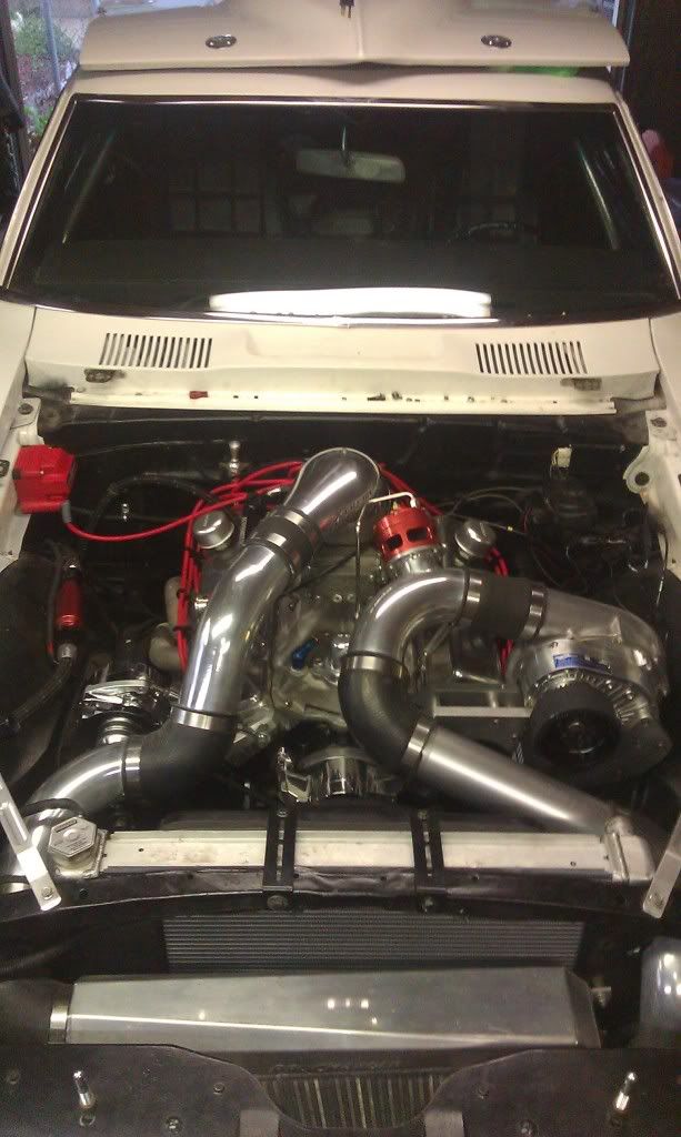
Pic isnt overly clear, what exactly is the problem ? Pipe too high ? Just cur/re-weld and adapt the end tank.
What routing are you intending to take with boost ?
shortest would be to rotate compressor, blow downwards ( if possible ) and 90deg into intercooler. Or possibly try and route over the top, doing a u-turn then into the intercooler.
Then swap intake plenum so inlet is on drivers side and blow boost into it that way
Or you could blow from blower across to driver side and into the IC.
Then blow back out under the blower and up into throttle as it sits now.
was thinking of cutting the pipe down then getting someone to weld an ally elbow back on, etc.
Posted: Fri Feb 22, 2013 9:27 pm
by stevieturbo
Just do whatever needs done, and fits easiest. And is also easy for maintenance etc.
There isnt really any right or wrong. Just try and keep it as smooth as possible.
But even with lots of 90's it'll still work well. So dont get too hung up on it.
Posted: Fri Feb 22, 2013 9:31 pm
by stevieturbo
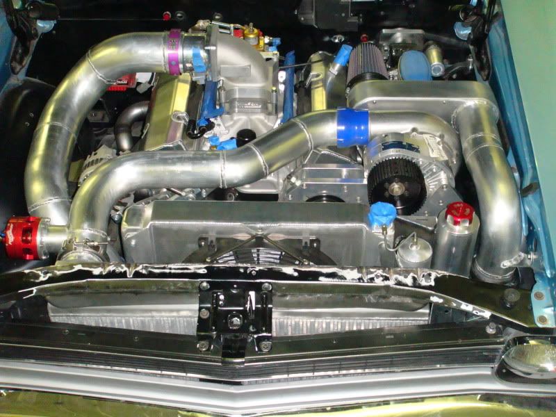
Another example. Although their IC enters and exits the same side, but you get the idea.
Posted: Fri Feb 22, 2013 9:32 pm
by Coops
cheers mate
Posted: Fri Feb 22, 2013 9:33 pm
by stevieturbo
Or another ( UK car it seems ). Take a look through the Yellowbullet link, there's loads of them
Posted: Fri Feb 22, 2013 11:32 pm
by Coops
cheers mate,
looking at how tight a 90 silicone bend i can get, i can shorten the pipe a bit but then i wont have a bead on the end,
Posted: Sat Feb 23, 2013 6:39 am
by Eliot
Dont worry about the bead - quality hose using a quality "mikalor" clamp will hold it. None of my dakar pipework is beaded - it did blow of when using shite non genuine jublie clips, but the mikalor's hold it together.
The intercooler pipework kits on ebay are OK, but the blue hoses are made from soft PVC, not silicone. But for the price they are fine for mocking up what you want - then purchasing the correct silicone ones after.
Posted: Sat Feb 23, 2013 9:24 am
by Coops
Thanks Eliot,
i may just do that buy some cheap 90 bends etc to mock up then get Roose to supply the hoses again,
thats a relief regarding the beading,
Posted: Sat Feb 23, 2013 10:07 am
by stevieturbo
You can buy all sorts of tight bends, be they silicone or cast alloy.
Cast alloy are the tightest, with silicone close behind
the less joins the better though.
Bead will largely depend on boost used. Low boost = less force so less essential, but it is good practice.
A few short beads welded around the pipe are more than enough. It doesnt need a full 360 bead. 4 x 15-20mm long is more than enough
I would never recommend Mikalor. They are big, bulky and when tested often leak.
If it's t-bolt style clamps, make sure they are thin banded types. Not the hick Mikalors.
Or pretty much any decent quality stainless clamp will be adequate. I'm using some Breeze constant torque clamps at the minute. Just a fancy worm drive really. Murray clamps are another popular version
Thin type. Overlap section is virtually flat
The Mikalor. Because they use a separate piece at the overlap, it adds bulk and at the interface section it doesnt clamp properly. Ive pressure tested them loads of times, and almost always there is an air leak at that point. it's only small, but that's not the point.
Murray clamps
Breeze
Posted: Sat Feb 23, 2013 10:21 am
by stevieturbo
Coops wrote:cheers mate,
looking at how tight a 90 silicone bend i can get, i can shorten the pipe a bit but then i wont have a bead on the end,
if you can get bits welded together to make the entire unit neater with less joints, it would be worth doing.
Or I'm sure if you mate a metal template hose in one piece, Roosie could fabricate a 1 piece silicone hose.
Just not 100% sure of what is required of a template.
But this gives you an idea.
Posted: Sat Feb 23, 2013 10:44 am
by Eliot
Steve is right about the mikalors thinking about it - they are bulky and that bit in the middle does move around and needs fettling to get right.
I like the first one he shows.
Posted: Sat Feb 23, 2013 10:50 am
by Coops
thanks guys,
i may cut the offending pipe back, get a reducing elbow to step it down to o/e size of the pipe stub (it has been swaged down from outlet pipe to stub) then this should work and give enough clearance to use the elbow,
i was thinking about leaving the plenum as is, and blowing out of the charger in to the intercooler on drivers side, then back out on passengers side an into the plenum,
The recirc valve goes any where between charger outlet and plenum yeah?
and IAT sensor fit into the plenum somewhere? or intake pipe before??
Posted: Sat Feb 23, 2013 11:05 am
by stevieturbo
Obviously hard to tell from photo about heights, clearances etc.
But yes, from blower over the top of the engine to IC at drivers side. Fairly straight and simple.
Then blow back out, under the blower and up into the plenum.
Only downside with this, it may restrict air filter space slightly ? Although looks like you can probably get an air filter clamped directly onto the blower, so should be compact anyway.
In this instance, I'd be inclined to mount the IAT sensor between the IC outlet and blower position. This should keep it away from most hot stuff so there is less chance of a false heat soak reading when stationary or moving slowly.
Plenum would be a bad spot, as would the pipework routed over the hot exhaust manifold
Posted: Sat Feb 23, 2013 2:40 pm
by Ian Anderson
Instead of a bead
Drill a number of holes around the circumference of pipes.
Insert pop rivets in said holes
slip hose over pipe and pop rivet heads then fit jubilee clip