Page 4 of 9
Posted: Mon Jan 25, 2010 10:53 pm
by Darkspeed
Couple of start graphs as I build up the library
People asking about how well a SD1 flows compared to a P6
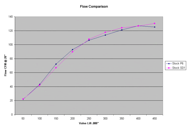
This is with a simple 30 degree back cut on the P6 38mm valve
Considering that max lift is at .390" !!
Posted: Tue Jan 26, 2010 1:41 am
by HairbearTE
That backs up what we were saying about the earlier heads.
Posted: Tue Jan 26, 2010 7:57 am
by ChrisJC
Do you have any idea of the margin of error / repeatability on those graphs?
Chris.
Posted: Tue Jan 26, 2010 2:04 pm
by Darkspeed
As the bench is a comparitor - Just a stick with a couple of marks on it - it's as accurate as it gets when making back to back measurements at the same time. Which is how these comparisons were made.
Different days have different environmental contions - the stick expands if you like - so for measurements taken on different days correction factors must be applied.
These are just same day back to backs
Testing on a cold day and on a very very cold day the flows on the same head vary by about 3%.
I have a weather station now

so I can measure the atmospheric pressure temperature and humidity so can apply these factors and get week to year comparisons
Still learning with the bench and it throws up some very interesting and unepected results.
On the P6 head above I was expecting poor results as the port tested is full of lumps bumps and all sorts of casting imperfections.
I will post up what we found with a home ported Stage 1 and a Medium valve Stage 3 later.
ChrisJC wrote:Do you have any idea of the margin of error / repeatability on those graphs?
Chris.
Being a devout sceptic myself I find the bench a most enlightening device many thing that have been written by D Vizard and the like just defy logic and I used to think to my self that cant be right - having the tools to recreate experiments and confirm that the results are correct is fantastic.
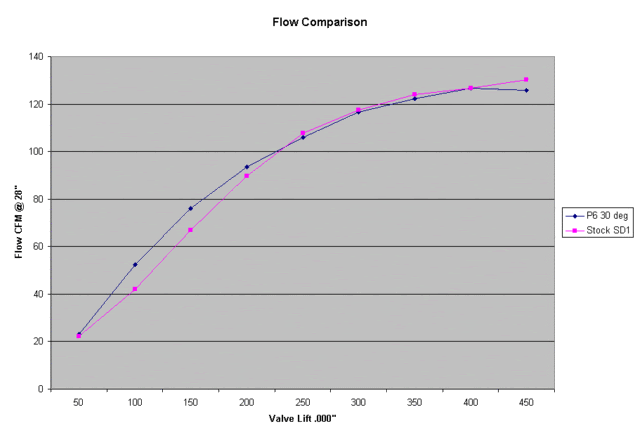
A 30 degree backcut on the valve on an waisted Vitesse/3.9 valve picks up flow just like the P6 above - but then loses flow at higher lifts unlike the P6 valve.
At the moment I am just playing, experimenting and learning and I expect to make more than a few mistakes along the way.
Andrew
Posted: Tue Jan 26, 2010 5:57 pm
by Darkspeed
Posted: Tue Jan 26, 2010 7:21 pm
by bigaldart
The graphs do confirm that the early heads are as not as bad as you would think compared to the SD1. C'mon, stop holding out and give us the Merlin low down

Alan
Posted: Tue Jan 26, 2010 8:00 pm
by Darkspeed
Quick post to show the flow graph for the Merlins
Because it was such a strange choke and drop off in flow this aspect was checked and checked again as was the STG 3 flows against the STG 1(quick home port job) flows.
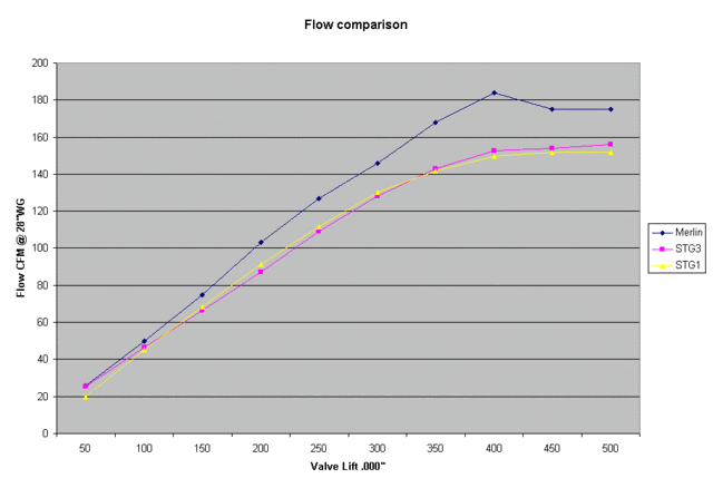
As was reported previously the Merlin graph looked very promising and up to .400" was mighty impressed and expecting to see 200CFM by .500" the sudden and unexpected drop in flow was a real disappointment.
The issue is with the port - as it flows the same maximum even with the valve removed.
As for the STG3 I a still have the head ( Cheers Marcus) to investigate it further.
Andrew
Posted: Tue Jan 26, 2010 10:44 pm
by Darkspeed
A couple more charts.
First up is a chart for DJE heads taken from an old DJE catalogue which was a poor photocopy so the graphs are at best a representation.
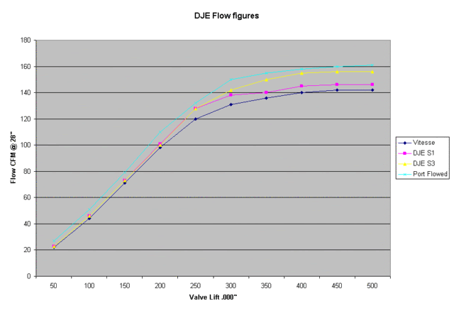
This is an overlay of the DJE S3 graph and the STG 3 curve just for interest.
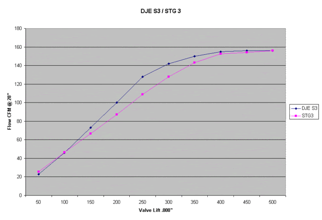
Cant really take much from this one other than the graph shapes the actual figures cannot be compared because of the different benches used.
Andrew
Posted: Tue Jan 26, 2010 11:55 pm
by CastleMGBV8
Andrew,
Have been following your thread with interest as have done some research in the past re Buick 300 heads which I have on my 4.35 Rover engine which I built and fitted last year.
A lot of my information came from Dan Jones in the states who is always helpful and informative and I suspect that the Buick 300 data you have probably originsted from him.
Here's a link to some of his data he posted on the Leyland P76 site a few years back.
http://www.leylandp76.com/technical/tech-headflow.html
Another thing which always leave me mystified is that if you use an Edelbrock 500 on a decent inlet on a 4.6L it will provide enough fuelling to support approx 280 BHP however according to Dan the actual flow of that carb is only around 430 CFM because of the way they measure and quote their flow figures and the same applies to all US carbs.
As the carb is supplying eight cylinders that would imply that only an average of 53.75 CFM is reaching each port way below the flow potential of the heads, of course the engine is not drawing on all 8 cylinders at the same time but at peak RPM it their cannot be much time betwen individual induction strokes, any thoughts?
I did have a link to Dans own site but can't find it at the moment, he does post on the British V8 forum so might be worth posting a link to your thread there and see what responses come up.
Kevin.
Posted: Wed Jan 27, 2010 1:26 am
by HairbearTE
I'm not sure that the cfm of the carb restricts the engine in the way you suggest. Nascar engines in the states that are restricted to 358ci and a single 390cfm carb make 780bhp. yes if you change to a much bigger carb the same engines make 850bhp, but they still make 780 on a single 390.
Posted: Wed Jan 27, 2010 10:31 am
by CastleMGBV8
Bear,
You had me going there for a moment, the current NASCAR engine specs are for the carb to be restricted to 830CFM.
http://www.hotrod.com/techarticles/hrdp ... to_06.html
My post was not suggesting that the carb was strangling the engine just that the flow was sufficient to provide a certain power level whilst the flow figures for heads would suggest a much greater flow potential and higher power output which does not appear to be the case, just one of the things my aged brain can't quite understand.
Kevin.
Posted: Wed Jan 27, 2010 10:48 am
by kiwicar
Hi
How would a 390 cuft/min in anyway restrict an engine with heads that only flow 175 to 200 Cu ft/ min? If the valves opened instantly to full lift and you had a 230 degree cam you would look at a maximum possable flow of 400 to 500 cuft/min and there is no way a flat tappet cam holds the valve fully open for more than about 20 degrees.
Or did I miss somthing??
As regard the chevy application, that carb body can be got to flow over 550 cuft/ min with basic gas flowing and on an sb2 engine that is big enough.
Best regards
Mike
Posted: Wed Jan 27, 2010 12:37 pm
by CastleMGBV8
Mike,
As I said it's not something I fully understand which is why I was asking the question.
Guessing that the average flow of one cylinder on the Rover with heads that will flow say 175CFM at .50 would be in the region of say half that for the full opening period then the actual flow for one cycle could be approx 85CFM x 8 = 680CFM and the standard Edelbrock 500 actually flows 430CFM then the flow potential of the heads still appears to be greater than the carb, all this indicates is that I do not know enough about this complex subject.
Regards,
Kevin.
Posted: Wed Jan 27, 2010 12:52 pm
by Darkspeed
And please chant the mantra - Always check the test units.
Just like heads different manufacturers test to different pressure which distort the figures on carbs
From what I can quickly see holley used to test at 1.5" HG and other test at 28" WG
Carbs are sized for the engine capacity it's volumetric efficiency, RPM for peak power etc. I will dig out the formula. Head flow related but approached from a different direction.
Andrew
Posted: Wed Jan 27, 2010 1:10 pm
by Darkspeed
Hello Kev'
What is "one cycle" that you have in your calculation and how did you come to choose it?
Andrew