Page 4 of 6
Posted: Mon Apr 29, 2013 5:40 pm
by DaviesDJ
On the subject of 300 heads - am working on them now on my floating pressure ebench and have a little head scratcher. Experimenting with model clay on the port floor - filled the bottom .25 inches with no other port mods, the flow actually reduced ver slightly. Should this be the case?? Do the benefits of raising a port floor only kick in once the sides and roof (particularly cylinder wall side wall) expanded?? Also tried tapering ramp up at the entrance - isn't a huge loss of flow, but definitely less. Fixed lift of 0.35 inch lift fixed to keep things simple at the moment.
Posted: Tue Apr 30, 2013 8:00 pm
by DaviesDJ
And on that guys, was thinking about using one of those 'liquid metal' heavy duty fillers to raise the intake port floor o the 300 heads, would like to weld up the floor but dont think a TIG torch would fit in well enough to o an efficient job. Does anybody have any experience of this, do any of you guys who have 300 heads have raised itake floors, and if so gow did you do it?? Cheers Guys, Dave
Posted: Wed May 01, 2013 9:16 am
by kiwicar
Hi
I have not done 300 heads, but on the question of filler I used high quality epoxy (a chemical resistant grade) and aluminiumy powder as a filler, on my inlet manifold and so far it has stuck fine, I run methanol. You need a good key for the stuff to stick properly but once on it stays.
Best regards
Mike
Posted: Sun May 05, 2013 9:42 pm
by DaviesDJ
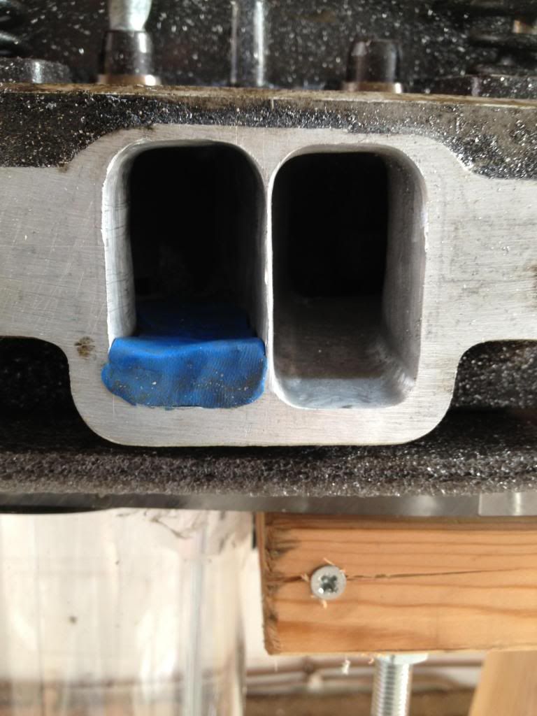
The thing that makes me scratch my head is the value of filling the intake port floor and to what extent - after opening up the roof and blending I have began filling the bottom 1/4-1/3 of an inch of the port and testing it on my floating pressure bench and then checking Flow on my floating pressure bench, seeing very little change in flow, if anything at all when I fill and blend, admittedly this does indicate greater flow velocity - admittedly my simple flow bench uses a Hoover and a calibration plate so not ideal. What sort of floor mods has anybody else made on rover / or 300 heads and what gains have been seen. Have a set of practice heads now working on. But do wonder if they will still be usable, have I taken too much material from between the middle 2 ports?? I will try and ost a pic [/img]
Posted: Sun May 05, 2013 9:50 pm
by DaviesDJ
Posted: Mon May 06, 2013 4:19 am
by ged
Hope this helps.
Find the "links to share this photo" box.
Left click on IMG.
Image URL will change to copied so you can paste elsewhere.
Regards Ged.
Posted: Mon May 06, 2013 5:47 am
by unstable load
I think the changes they talk about are to do more with flow patterns and velocities, which are beneficial to maintaining fuel/air mixture and atomisation.
There is a limit that ports can go before you are wasting time, and actually going backwards.
Posted: Tue May 07, 2013 11:58 am
by topcatcustom
When flow testing these- are you using any kind of inlet manifold/trumpet etc, as I don't think you will get a true reading without. The air entering the sharp edged runner as in that picture will be causing a lot of turbulence and restricting the flow, you may find better results even if you put a plasticene "hump" around the inlet, to smooth the air entering the port. This could show more of a difference between the one with the floor filled and without.
Posted: Tue May 07, 2013 12:22 pm
by kiwicar

also what range of valve lifts are you testing for? and how far into the port are you "lifting" the floor I see you have Knife edged the devider, I take it that you have already opened the port face quite a way??
Best regards
Mike
Posted: Tue May 07, 2013 6:07 pm
by DaviesDJ
For simplicity I am measuring at 0.2 0.3 and 0.4 inches, the filling goes to the short turn and "blends". These are practice heads, seeing what expansion on the cylinder wall side would do, thought I had written them off by doing this but can you use them knife edged or do they leak air too much?
Posted: Tue May 07, 2013 6:09 pm
by DaviesDJ
And as you say, even if the flow is similar by eliminating dead space velocity is improve - these are not 300 heads they are practice rovers
Posted: Wed May 08, 2013 9:14 am
by kiwicar
Hi
This is a very complex thing you are trying but from what I know. . . when you lift the port floor like this you need to be very carefull not to get the port to taper the wrong way, you aim of blending into the short turn radius is spot on but you need to ensure you do not have an increasing cross sectional area as you get closer to the valve, you need a taper of about 5-7% from the start of the port after the bowel behind the valve to the mating face ie you may have to lift the floor of the port a little more at the short turn radius. You probably need to raise the roof of the port at the mating face by more than you have to get good results, not sure here but I would experiment. Not quite sure what you are doing at the port entrance but to get sensible results you will need a minimum of some sort of bell mouth or representation of the inlet runner otherwise the port entrence turbulance will dominate everything you are trying to measure.
Personally I would try and chop one runner off a scrap manifold a with it's section of plenum floor/wall and bolt that on when you flow test. the knife edging can be recovered with a little epoxu filler, or just live with it, if you have a step from the manifold face to the port entrence and only have a gap of less than 2mm you should be fine.
Best regards
Mike
Posted: Mon May 27, 2013 9:08 pm
by DaviesDJ
Ok guys, along with collecting bits for my latest project am starting to port the 300 heads to go on them. Started pretty basic by smoothing down hose huge spark plug bosses, and polishing the chamber, new seats and valves to go in etc, and bullet guides. BUt was wondering how the other/previously ported 300 heads had been approached. My plan was to weld/epoxy up the floor 5-7mm or so and blend that with the short turn - the. Open the cylinder wall side about 1mm and the other side perhaps a little less, and the roof about 2-3mm - obviously throats to be opened and blended - 30 degree cut back on the valve and a carefull 3 angle valve job. Was wondering if other (better) guys had approached it differently with these heads? Thinking of bowing out the cylinder wall side also to encourage swirl. Has anybody left the floor as it is?? Want good mid and top end power - track car only.
Posted: Tue May 28, 2013 12:32 pm
by Darkspeed
Until you hog out the throats you do not move the restriction to the port. The restriction is still the throat so you will not see an real flow changes with the floor and manifold end of the port.
Get some flow balls made up and find where the restrictions are first.
ETA - this regarding the work you did on the rover heads
Posted: Tue May 28, 2013 3:19 pm
by DaviesDJ
wasnt happy with those rover heads:-) using them to learn and get myself better. One thing I have learned is that 'big' port is not the way to go, it made minimal difference as everybody predicted;-) but did a lot of learning in terms of how far one can go etc. But filling the floor definately helped velocity. even if it did not really help flow overall - with a cotton thread you can easily observe that on the floor the air flow in turbulent and the pressure high, the other thing i have noticed is that filling the floor alone doesnt help but this in conjunction with tightening up of the short turn could, but i havent got that far yet. Dont want to ruin my 300 heads as i only have one set. When I cut the 1.77 inch valves I will send the serdi down the throat trying to match it as close to the guide as i can. Does anybody with 300 heads have an idea of how their heads were set up? were the port sizes kept to standard? I think they look big enough but what do I know. Dream is to go the other side of 400 BHP (i know you are all laughing). Also, is anybody in the midlands wanting to meet up and chat about this stuff??

