Page 3 of 4
Posted: Wed Dec 11, 2013 5:36 pm
by DaveEFI
So what you're saying is you must never run a say 100 amp alternator at or close to 100 amps output? So what is its maximum safe output?
Posted: Wed Dec 11, 2013 6:17 pm
by stevieturbo
DaveEFI wrote:So what you're saying is you must never run a say 100 amp alternator at or close to 100 amps output? So what is its maximum safe output?
No. I am saying
I would not want to run the alternator at or very close to it's maximum for extended periods.
Doing so is bound to increase the chances of failure.
Others can do as they wish.
Posted: Wed Dec 11, 2013 8:04 pm
by richardpope50
Sorry if I have confused anyone, but the 100 amp fuse is simply the fuse that was on the engine between alternator and battery terminal when I got it. It is also a 100 amp rated alternator that was on the engine too.
My 70 amp fuse is the rating I chose to protect my junction box based on my calculations. So far I have not measured any current and that's why I want to buy an ammeter - now ordered.
The 0.8 volt drop by the ECUs is detected simply by removing fuses and the only circuit left was the ECUs so they account for 0.8v without engine running. This seems OK to me but no idea on amps (yet).
When running, my calculated typical amperage is about 65 amps but I want to measure this in case it is different. Clearly when running, coil packs, injectors and fuel pump, etc, are in this calculated 65 amp figure.
My 70 amp fuse is a midi type fuse rated at a continuous 70 amps with a blow amperage of 120. I can easily replace it with a higher rating, I suppose, as all my sub circuits are protected by fuses - 25 of them!
It could well be that the 70 amp fuse just runs hot and is melting the plastic mounting block but I want to check to see if the current is very high. I also do not quite understand the reason why the alternator (across battery) shows. 13.2v
... and now I have to wait for some oil and water gauge senders that are now on a delayed delivery until mid-Jan so cannot start engine until at least then! What fun.
Posted: Mon Dec 16, 2013 9:23 pm
by richardpope50
Finally extracted the melted fuse holder. Hmm. OK, the plastic was simple trunking but it must have got really hot. I note the fuse never blew so is this heat normal? Anyone know?
No other cable / wire seems to have got hot at all, only the fuse holder.

Posted: Mon Dec 16, 2013 9:31 pm
by stevieturbo
Terminal and fuse look sensible. Buy the current clamp I linked to. You need to know for sure what's going thru it
Posted: Mon Dec 16, 2013 11:33 pm
by DaveEFI
How are the terminals fixed to the cable? Assuming it is a fuse holder designed for a 100 amp fuse, I'd assume the fuse contacts to be up to the job. Which leaves the connection to the fuse holder suspect. Somehow.
Posted: Mon Dec 16, 2013 11:46 pm
by stevieturbo
Would the cable not attach to the two bolts, same as the fuse ?
I bought one of these for my own car, although never bothered using it in the end
http://www.amazon.co.uk/All-Trade-Direc ... B00904NE14
Other similar items
http://www.asap-supplies.com/marine/fus ... -and-boxes
Posted: Tue Dec 17, 2013 9:10 am
by DaveEFI
I'd hope there were terminals on the cable to fit the studs. The problem therefore either being either the cable to terminal, or terminal to stud.
Posted: Wed Dec 18, 2013 6:29 pm
by richardpope50
The melted mounting simply consisted of the two M6 stainless steel bolts shown and the input cable had (still has) a 6mm crimp ring connector. The output to the distribution is actually two cables each with 6mm crimp connectors - just two thinner cables used instead of one thick for internal convenience.
Fuse mounting block similar to Amazon one now fitted. It has 5mm studs so 6mm ring connectors now attached to 5mm. New 70 amp fuse has 5mm mounting holes whereas I had drilled old one to 6mm to suit M6 bolts.
Clamp meter has arrived but have to wait until mid-Jan when new temp gauge senders are due - currently cannot fill oil and water sender holes so cannot start engine!
As 70 amp fuse never blew, amperage cannot have been that high and was probably at 45 or so amps.
Posted: Wed Dec 18, 2013 7:16 pm
by stevieturbo
most 6mm^2 cable would not be rated for 70A
The megafuse holder I bought was M8 studs
And what sort of ring terminal crimps are you using ? A lot are dung and far from ideal for handling a lot of current. Especially if it is continuous load.
Bolts in the picture look bigger than M6 though ?
Posted: Thu Dec 19, 2013 12:02 am
by DaveEFI
What sort of terminal and how where they crimped? My guess is the crimp was to blame in some way - there's not much else, assuming the bolts were tight, and the terminal in direct contact with the fuse. Although it's more common to use brass rather than stainless steel bolts for electrical connections.
Posted: Thu Dec 19, 2013 7:26 pm
by richardpope50
Hmm.
>most 6mm^2 cable would not be rated for 70A
Good point and I need to measure the size. It is quite thick but just maybe ..
My connection from this 70a fuse to my distribution panels are two 38amp cables so perhaps I need to uprate these too.
>The megafuse holder I bought was M8 studs
Mine has 5mm and is the holder to match the 70 amp fuse I bought (together).
>And what sort of ring terminal crimps are you using ? A lot are dung and far from ideal for handling a lot of current. Especially if it is continuous load.
Halfords blue ones(!)
>Bolts in the picture look bigger than M6 though ?
Nope, my M6 stainless steel stock
So just maybe I need a revision ... Thanks for the clues
Posted: Thu Dec 19, 2013 7:40 pm
by DaveEFI
80/0.40mm, 10mm/sq, 70amp.
56/0.30mm, 4mm/sq 39amp.
You'll have to do same maths if measuring a cable to know what it is as the figures given are for cross sectional area.
However, it's not the cable which is the problem here but the connection between it and the fuse, as that's where it's melted.
Posted: Thu Dec 19, 2013 8:02 pm
by stevieturbo
Blue typically denotes cable size....in case of blue, I think it's about 2.5mm^2 max ? Maybe at a push 4mm, but dont think so.
Any pics of the crimps ? Preferably before everything melted lol
This is the style more typically used in the electrical world. And they're usually much sturdier than the coloured variety. Still cheap too. And dont forget to use a good quality crimp tool
Bit of heat shrink or tape will tidy the look up.

Posted: Fri Dec 20, 2013 12:01 am
by DaveEFI
I'd personally never use pre-insulated terminals on car cable - they're more for solid core mains wiring. As proof, crimp one then cut off the insulation and look at the crimp. It is poor. A proper crimp grips the conductor all the way round - achieved by using a heart shaped crimper which shrinks the terminal round the conductor, not just flatten it. Like this:-
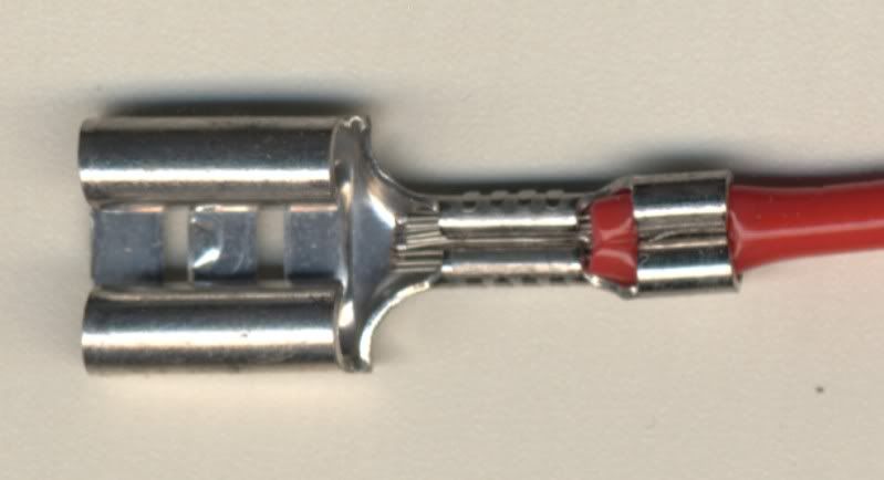
Other thing is there are some very poor quality pre-insulated terminals out there making things even worse.
With any crimped terminal, you must use the correct tool. And they can be expensive. This is far more important when running a cable/terminal close to its maximum rated limit.
