Page 3 of 4
Posted: Sun Jun 12, 2016 5:08 pm
by Ian Anderson
Great protect and kudos to the Ausies and Kiwis who do all this reverse engineering and making things work together
http://www.gt40s.com/forum/gt40-build-l ... -up-7.html
Shows some ducting and 4 inch bilge room air pumps that move 250 cfm on my car.
Sorry that is post 132
Dreamt for directing cooling air into engine bay to help with cooling around an engine in a dead space
Ian
Posted: Sun Jun 12, 2016 9:47 pm
by roverv8bay
G'day all. Ian thanks for the pics an idea well worth looking at VW supplied the perfect item in the factory heater fan for the late bay bus I have 2 of these so in they go

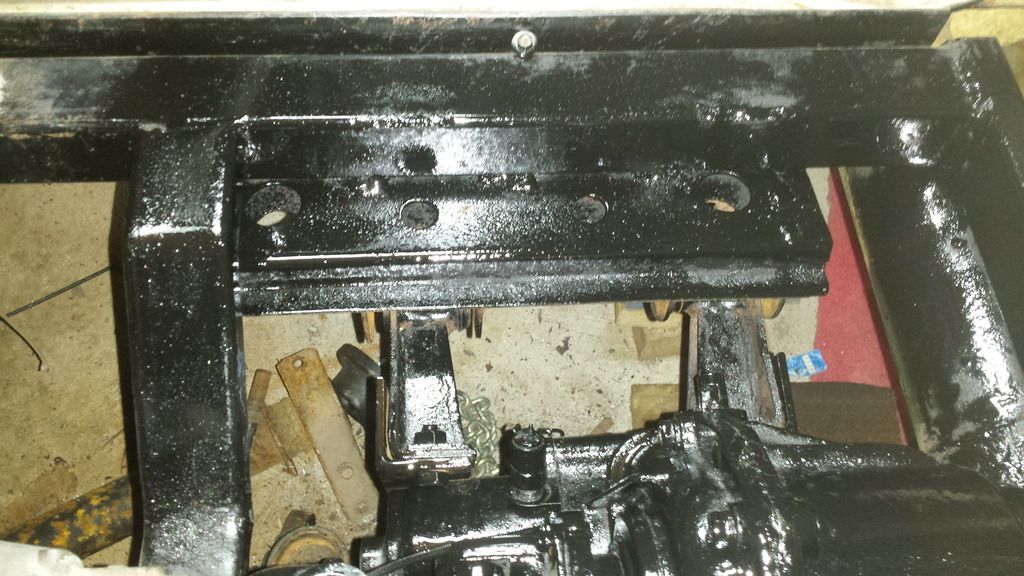
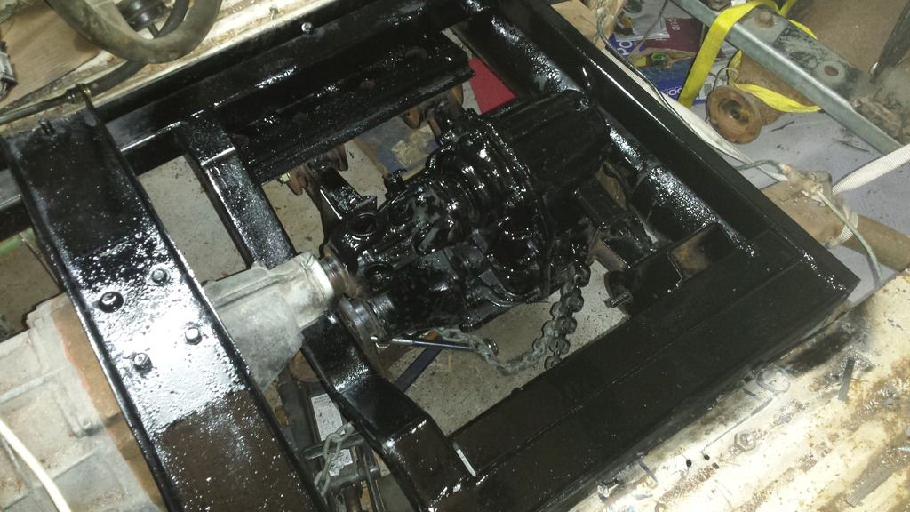
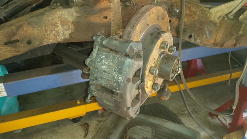
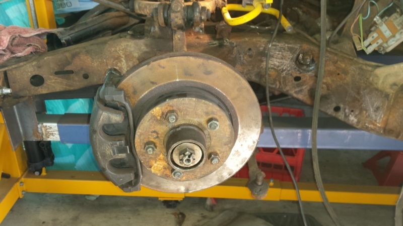
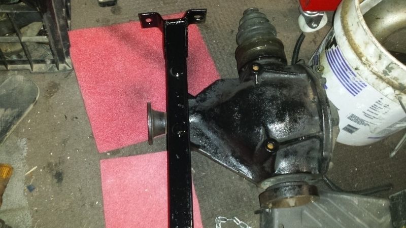
Front diff crossmember
Posted: Fri Jul 29, 2016 12:40 pm
by roverv8bay
DOH
Posted: Fri Jul 29, 2016 12:42 pm
by roverv8bay
Posted: Sun Jan 01, 2017 6:25 am
by roverv8bay
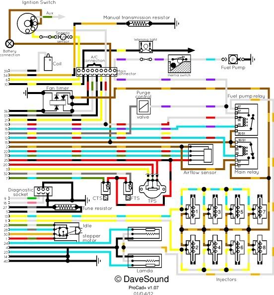
Happy New Year all. From Australia. Now to the point can anyone help me with a very basic engine wiring diagram for engine alternator & senders to run a cux14 3.9. I have a good manual but it has 2 different sets of wires some on 1 page pre 95 then matching others on post 95. Confusing me so please let me know. I have a Facebook page if that helps Called modified KOMBI'S & Vw projects. thanks in advance for any help sent my way
Posted: Sun Jan 01, 2017 10:07 am
by DaveEFI
Does this one look correct? it's the earlier of the two I've done.
Posted: Sun Jan 01, 2017 11:37 pm
by roverv8bay
G'day DaveEFI. thanks mate this will be a great help. now I have a drawing that makes sense. the Haynes has 2 that seem to cross over. All the best for the New year.
Posted: Mon Jan 02, 2017 5:32 am
by roverv8bay
Good afternoon Dave Can you tell me where & what to look for the transmission resistor I have tried to find a pic of 1 on google
Thanks Ernie
Posted: Thu Jan 05, 2017 11:37 am
by roverv8bay
Another part I can't find is the purge valve does anyone have a pic of what it looks like & where it should be on the 3.9 motor. google shows a lot of different items confusing as they all claim to be purge valve.
thanks for any help
ernie
Posted: Thu Jan 05, 2017 2:18 pm
by DaveEFI
Can't really help with either as I've never had a hotwire motor. Only did the schematics as I was bored.

Posted: Thu Jan 05, 2017 3:21 pm
by Ian Anderson
Purge valve was an emissions job. It connected from memory to an air bleed on the fuel filter and opened once engine was hot and at constant revs like motorway cruise.i have nothing connected and it does not appear to have any side effects. As you say so much conflicting info about on google so I tried with nothing and ten years later still have nothing connected!
My reasoning at the time was why would you ever want to bleed air fron a recirculating system anyway? As the fuel goes through the rail and then the pressure relief valve and flows back to the tank. Air bleed on a loop like this would in my opinion mean pure fuel being bled into the air inlet causing a really rich ooverload.
Ian
Posted: Fri Jan 06, 2017 7:51 pm
by roverv8bay
G'day all. Well what an easy task with only 1 diagram instead of 2 tool work off. Thanks to David. Ian thanks for the info on purge I found it. unfortunately we have to use what ever the engine came with to get reg. saving grace is no cats from factory. Keep watching if you see where I may be headed the wrong way with any of the rover stuff let me know. Always welcome advice.
Posted: Sat Jan 07, 2017 9:49 am
by DaveEFI
The diagram is actually a standard CAD file. If anyone would like that so they can add to it or modify for their own use - or a PDF so it can be resized without loss of quality - PM me with an email address.
Posted: Sun Jan 08, 2017 12:36 am
by roverv8bay
G'day Dave. What can I say. the info was very useful. Thanks for your time.
I often sit back after reading these post & think what a great community the car people share. To be able to communicate what I need to so many diverse people around the world. To everyone out there thanks for being Car hobbyists & sharing your knowledge.
Ernie
Re: mid mount roverv8 4x4 kombi
Posted: Sat Feb 24, 2018 11:50 am
by roverv8bay
Good day all. I have been busy sorting all the little jobs. relocating the brake booster master cylinder & clutch master cylinder. Also had the final machining on the rear tailshaft. How can i post pics now Photobucket really did the job on our shareing.