
Could anyone point me in the direction of a good diagram for th oil pump / relief valve assembly.
As I wasn't the one who took it apart, I really don't want to second guess anything when it comes to the oil system.
It's for a late crank driven pump by the way.
Thanks....Paul.
OIl pressure relief valves / oil pump assembly
Moderator: phpBB2 - Administrators
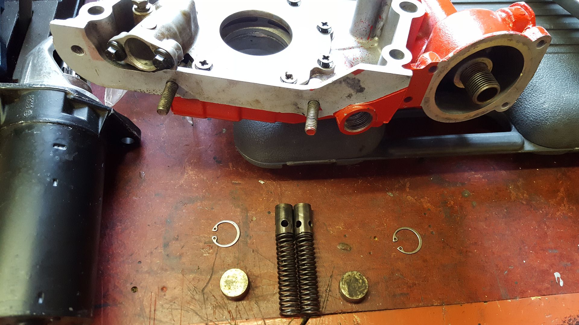
There are two types of front covers with the crank driven oil pump.
If it an interim type cover with a distributor then it has one pressure relief valve.
If it's a P38 type cover (no distributor) then it has two valves, one for pressure relief and the other for oil cooler flow diversion.
Which have you got?
If it an interim type cover with a distributor then it has one pressure relief valve.
If it's a P38 type cover (no distributor) then it has two valves, one for pressure relief and the other for oil cooler flow diversion.
Which have you got?
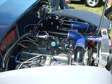
1950 A40 Devon Hotrod with 5.0 twin turbo RV8.
EDIS8 wasted spark, Holley Injection.
Been as far as the Moon and back in 57 years of driving. Same Car, 5 engine upgrades !!!
EDIS8 wasted spark, Holley Injection.
Been as far as the Moon and back in 57 years of driving. Same Car, 5 engine upgrades !!!

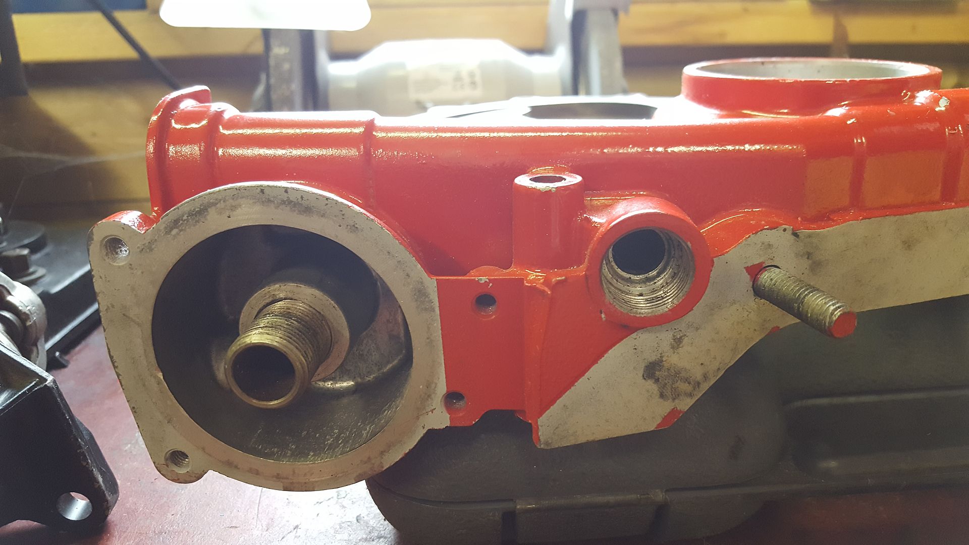
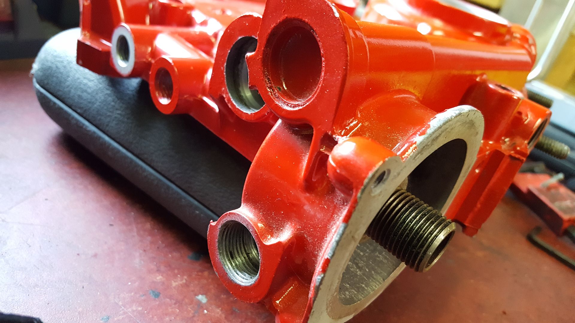
I think it would be better to run the oil cooler via the M20 x1.5 threaded connection points. This will make the oil cooler work as originally intended in the p38 vehicles.
When you connect the remote filter, make sure the inlet and outlet flow in the correct direction. The correct direction is when the flow is from the outside of the element towards the centre of the filter.
When you connect the remote filter, make sure the inlet and outlet flow in the correct direction. The correct direction is when the flow is from the outside of the element towards the centre of the filter.
1950 A40 Devon Hotrod with 5.0 twin turbo RV8.
EDIS8 wasted spark, Holley Injection.
Been as far as the Moon and back in 57 years of driving. Same Car, 5 engine upgrades !!!
EDIS8 wasted spark, Holley Injection.
Been as far as the Moon and back in 57 years of driving. Same Car, 5 engine upgrades !!!
