Rover V8 cylinder head porting advice.

General Chat About Engine Build

Moderator: phpBB2 - Administrators

3xpendable
Getting There
Getting There
Posts: 192
Joined: Thu Feb 11, 2010 8:46 am
Location: South Wales

Rover V8 cylinder head porting advice.

Post by 3xpendable »

I'm at the stage of my build now where I'm rebuilding the cylinder heads on my 3.9 Rover V8 and before I get too tucked in I wanted to get some advice on what best to do in terms of porting and blueprinting. This is for a road car, so I'm not after massively opened ports etc.

From what I've read the best setup for the heads is the following:

Match the inlet port sizes to the manifold gaskets
Clean up the inlet and exhaust ports, with 120 grit paper
Clean up the combustion chambers to a smooth finish.

Does that sound about right?

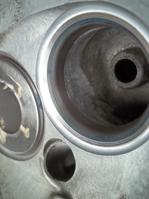
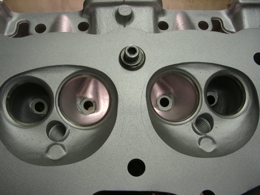
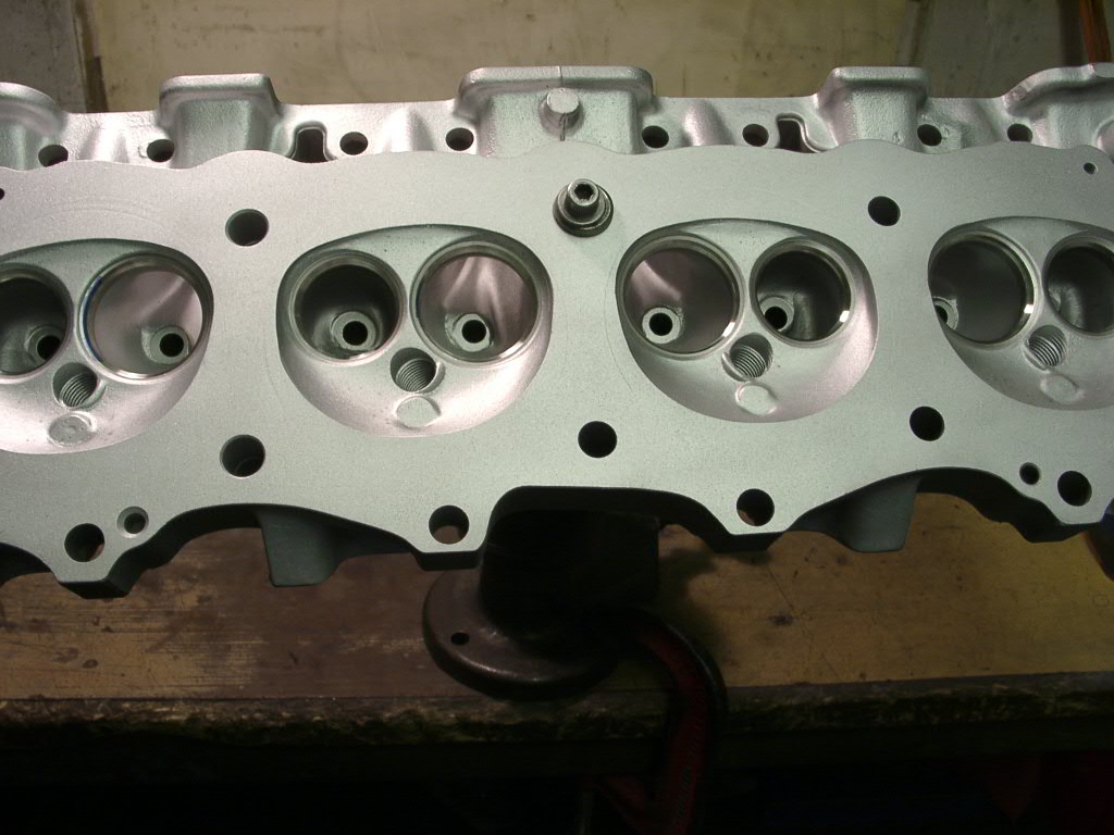
Here is one of my heads after I cleaned it, lightly faced up and cleaned the ports with cleaner:

Image

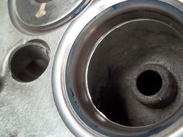
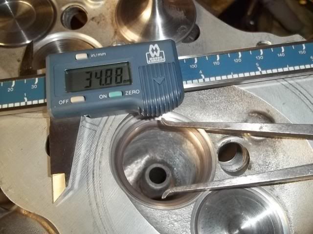
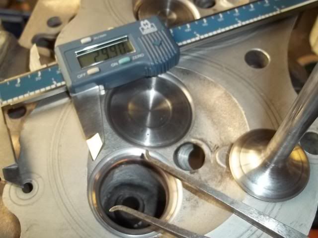
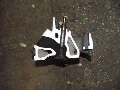
This is a combustion chamber before I had a go at it:
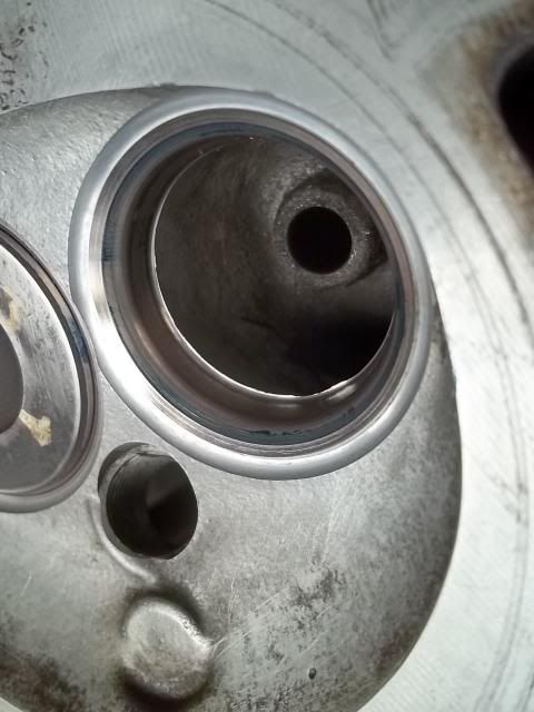
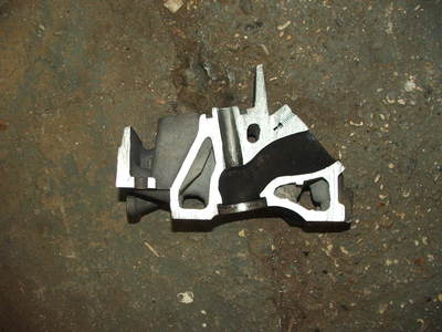
Image

And one after:

Image

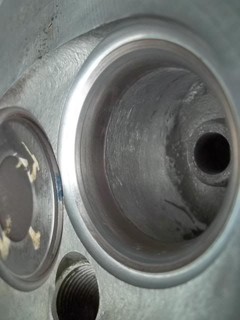
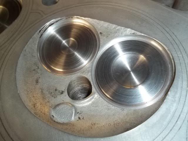
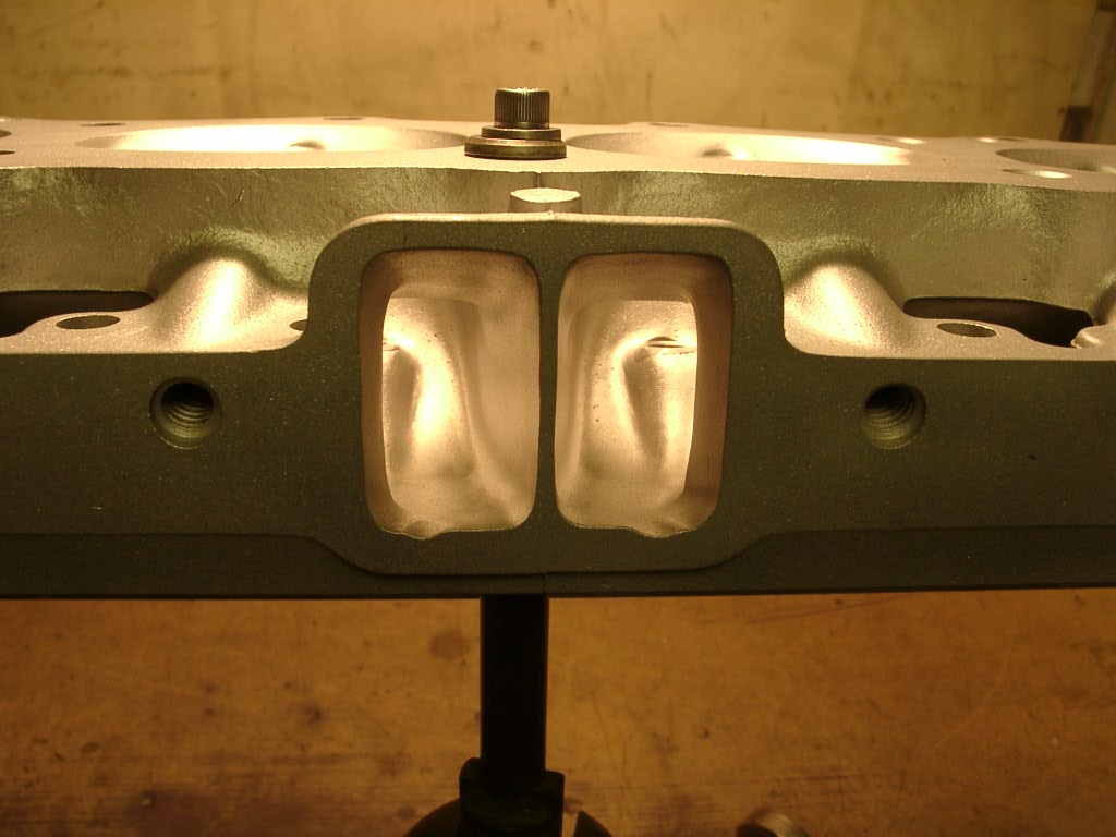
This is a close up of the same chamber after some cleaning and polishing with 360 grit paper, is that smooth enough or do I need to go coarser?

Image

Can that 'button' in the middle of the chamber be flattened out or not?

Many thanks


1971 MGB GT (V8 project)

mgbloke
Forum Contributor
Forum Contributor
Posts: 523
Joined: Thu May 17, 2007 6:05 pm

Post by mgbloke »

I am by no means an expert but have achieved good results from self porting rover heads. I would suggest that what you have done so far will make little difference. It is quite easy to remove material directly behind the valve seats then get a 3 angle seat job. I use a rotary burr in a drill works quite well. Don't take too much off just make it flow into the seat.

Mark

kiwicar
Forum Contributor
Forum Contributor
Posts: 5461
Joined: Sat Nov 18, 2006 5:00 pm
Location: Milton Keynes

Post by kiwicar »

Hi
"Match the inlet port sizes to the manifold gaskets "
this is just what you do not want to do on the rover, the port at the head face is already too large to get proper taper into the bowel area. If you are going to match the head to the inlet manifold do so by removing the absolute minimum of material from both, dowel the inlet manifold to the head then use templates to match the two. If you take the head face to the gasket then the port at this point will be vastly too large to flow properly and you will get less flow than unmodified heads. Concentrate on the ara wheree the port narrows to allow the pushrods past and open this area out and blend the area around the bowel don't touch the short tur side apart form very light blending to the seat. I would leave the combustion chamber pretty much alone apart from removing any sharp transitions from machined areas and de buring, leave that bit of ally by the plug alone. I would get those seats replaced and get a decent 3 angle valve job done, the seats look pretty badly receeded and in pretty bad condition, have you had LPG run through this engine in the past?
Ideally you want a finish in the ports that you get from 80 to 100 grit emmery cloth that is about half worn out on a rubber pad. Don't go much finer in the ports it is counter productive. As for chambers no finer than 120 grit but it all wants to be the same over the surface and chamber to chamber.
I would concentrate on getting all the valves seated the same distance into the heads and all the chambers the same volume.
Looking at the photos you have a lot of pitting on the head deck surface, before you put too much work into these heads check you can get them decked far enough to get a good cleam gasket surfaceand that the heads have not gone porous behind the chambers, they look as if they have spent some time with no anti freeze in the coolent.
Best regards
Mike
poppet valves rule!

User avatar
Darkspeed
Guru
Guru
Posts: 913
Joined: Sun Sep 02, 2007 4:43 pm
Location: Shropshire
Contact:

Post by Darkspeed »

To improve flow, the work is seat / insert / throat any work anywhere else is ultimately pretty pointless.

The 14 bolt heads do flow better than any other previous casting as the ports are a better shape and the smaller chambers un-shroud the valves a little more.

To get more flow you really have to remove metal.
4.5L V8 Ginetta G27

User avatar
Darkspeed
Guru
Guru
Posts: 913
Joined: Sun Sep 02, 2007 4:43 pm
Location: Shropshire
Contact:

Post by Darkspeed »

Here you go some assistance with what I consider to be a stage 1/2 tune

OK so the seats are a bit OTT with very trick radius cut profile and a 45 on the top but a good 3 angle would suffice. I had opened up the throat already but the radius cut took the exhausts out a bit more and I had to bend the throats again - The vernier gives the throat diameters shown. I have not finished lapping the seats in yet or blueing to check.

All the valves have a 30 degree back cut and the exhausts are full edge radiused.

Gave the valves a quick polish up with some 120grit emery paper.

Image

Image

A quick blend with a burr

Image

And a run over with a cartridge roll

Image

Throat diameter inlet

Image

And exhaust

Image

Probably will not touch the chamber on this head as standard valves and the radius cutter provides a nice entry. I will just knock off the sharp edges and that's it

Image

Hope that helps.
4.5L V8 Ginetta G27

kiwicar
Forum Contributor
Forum Contributor
Posts: 5461
Joined: Sat Nov 18, 2006 5:00 pm
Location: Milton Keynes

Post by kiwicar »

Hi
Very nice job.
Best regards
Mike
poppet valves rule!

User avatar
Darkspeed
Guru
Guru
Posts: 913
Joined: Sun Sep 02, 2007 4:43 pm
Location: Shropshire
Contact:

Post by Darkspeed »

Thanks Mike,

And as Mike indicates above about finishes - the throat finish was with an 80 grit roll and the valves were polished with 120 grit emery. 360 grit :shock: That's for bodywork paint prep would block in an instant and take for ever to get a finish that you don't want.

For valve seats - always blue them its easy to get a nice grey line on the valve and seat as the paste is yay thick and will not pick up low points or thickness variation - blue is the only way to ensure a good seal.

Also don't worry too much about the seat thickness being a little undersize on what you aim for - On this head I will lap in to about a 1.2mm seat and expect it to be around 1.5 once run in and the valve and seat have been hammered together for a bit.

I picked up a roll of 80 and 120 emery 50M rolls in screwfix when I got some cutting disc's recently - does the job a treat. £16 a roll and should last a while as I used about 1.5m for the whole operation :lol:

ETA - if I get a minute I will 120 grit a spare chamber and show the finish.

Andrew
4.5L V8 Ginetta G27

User avatar
Eliot
Top Dog
Top Dog
Posts: 1765
Joined: Sat Nov 18, 2006 9:46 am
Location: Milton Keynes
Contact:

Post by Eliot »

These are some heads my late father did for my mates v8:
Image

Image

Image

http://www.mez.co.uk/westfield/index.html

Seats were machined out for more flow but retained std valves.
Eliot Mansfield
5.7 Dakar 4x4, 4.6 P38 & L322 TDV8
www.mez.co.uk / www.efilive.co.uk

kokkolanpoika
Knows His Stuff
Knows His Stuff
Posts: 546
Joined: Sat Nov 25, 2006 1:25 pm
Location: Finland
Contact:

Post by kokkolanpoika »

Darkspeed:
I do not understand why you lapp those valves/seat´s if you have machined those parts in machine shop? Why to destroy all that work?
In these days usually machines are good and work is excellent.. So no need to lapp anymore.. Only if make an budget repair..
But it´s my opinion..
Timo

User avatar
Darkspeed
Guru
Guru
Posts: 913
Joined: Sun Sep 02, 2007 4:43 pm
Location: Shropshire
Contact:

Post by Darkspeed »

Hi Timo,

Because its a simple thing to do to ensure that the valve and seat are sealing correctly. Even with tens of thousands of pounds of Serdi equipment it has been found that when bluing the seat and the valve the contact can be irregular. A lot of the time it is OK to rely of the valve hammering itself into the seat and taking up and variance but its not much effort to take some fine paste and lap them in and then blue to ensure all is as you wanted.

Old habits die hard I guess :wink:
4.5L V8 Ginetta G27

kokkolanpoika
Knows His Stuff
Knows His Stuff
Posts: 546
Joined: Sat Nov 25, 2006 1:25 pm
Location: Finland
Contact:

Post by kokkolanpoika »

Of course there is many many opinion´s..
I have learn and hear that if you lapp those valves, seat angle will vary slightly, and it is not good as when it is machined with MIRA.. I have found when i try to lapp machined valves/seats in fine paste, it will made perfect contact every time..
Say 10years go, lapp:ing valves is ok, but these days it is unnecesary in my mind.
Of course all depends on machine shop quality and condition on MIRA and valve guide etc..
Timo

User avatar
ChrisJC
Top Dog
Top Dog
Posts: 5040
Joined: Mon Nov 20, 2006 1:13 pm
Location: Northants / Cambs
Contact:

Post by ChrisJC »

I chopped up some heads when I ported mine. It is pretty obvious where material should be removed from!

Image
Image
Image
Image

Chris.
--
Series IIA 4.6 V8
R/R P38 4.6 V8
R/R L405 4.4 SDV8

User avatar
SimpleSimon
Knows His Stuff
Knows His Stuff
Posts: 620
Joined: Mon Apr 25, 2011 10:36 pm
Location: East Sussex

Post by SimpleSimon »

:(
Last edited by SimpleSimon on Sat Nov 29, 2014 11:42 pm, edited 1 time in total.
TVR Chimaera RV8 Mods & Megasquirt

unstable load
Top Dog
Top Dog
Posts: 1278
Joined: Mon May 04, 2009 6:53 am

Post by unstable load »

OK, a question if I may.....
Side on, looking at the cut up heads it's pretty clear where to remove material, but looking into the ports in the second photo posted by Eliot, there is a narrowing from one side of the port relative to the manifold side. Is it just the angle it's viewed from or does it indeed narrow off about half way in?
Is there any work that needs to be done there to allow for improvements or is it just around the valve guide areas??
Cheers,
John

3xpendable
Getting There
Getting There
Posts: 192
Joined: Thu Feb 11, 2010 8:46 am
Location: South Wales

Post by 3xpendable »

Thanks guys, i've had a quick look through your posts and will study them in detail later.

I did head porting in my course at university so know the basic fundamentals, I just wasnt sure if there was anything specific to these motors. Its interesting that many of you say that I dont need to port match the inlet with the inlet gasket, is that correct?

Finally, i've cleaned them up a bit better and will get some pictures for you soon but already knew about the grits to use. Whats the best tool for taking metal off the ports? A dremel or a drill with the relevant attachment?
1971 MGB GT (V8 project)

Post Reply

Return to “Engines Area”