Page 1 of 7
Time to start wiring the car!
Posted: Tue May 09, 2017 10:42 am
by chodjinn
Hello all, been a while since I have been on here. Skyline coming along nicely albeit rather slowly. Just purchased a nice MS3PRO ECU and also have all my electrical bits sorted such as pumps and fans etc.
Now to the wiring. I am doing this from scratch/bare shell. I know there are websites and kits available etc. from the likes of vehicle wiring products, but I could do with someone who has a bit of knowledge to help me determine what I need to buy etc? As I have no idea where to start, and this is exactly the same point where my MGB project failed last time and I am determine to do it right. Stuff like fuse boards/relays etc. get my head in a mess.
What I am running;
MS3PRO with Innovate LC1, a ton of pressure sensors etc.
Bosch 044 & 413 pumps
Pacet 12" radiator fan
Pacet 8" heater fan
Rear brake lights / brake switch
Rear emergency/rain light
Wiper motor & washer motor
Couple of small gauges
That's it. Help greatly appreciated to get me started if possible, I have spent hours on google but I just get confused and lost in all the info when it comes to wiring. Cheers!
Posted: Tue May 09, 2017 12:22 pm
by DaveEFI
First thing you need to do is draw out a circuit diagram. You can do it in bits - main loom, injection, etc. Much easier to correct a mistake there than in the flesh. And do it in colour showing the actual wire colours you use. Not being sure of those at a later date is a PITA. Also best to do it on the computer so you can correct a wiring colour (etc) easily - if you change something later.
A decent CAD drawing prog is worth learning, as you should be able to find a library of symbols, or make your own. DraftSight 2D is one and free.
After the circuit diagram, you can also draw out a loom one, giving dimensions.
A major problem will be finding new connectors for car specific stuff - like say the windscreen wiper motor, etc. Some can be easy, some not.
Obviously if you have the old, it can be re-used, but with new terminals (if you can find them) rather than a spliced connection, where the wire changes colour.

If you get my drift.
There are several UK suppliers of wiring parts, but no single one seems to sell everything.
Cable is very expensive. Can be worth getting several old car looms from a breaker as a source of cable, if nothing else.
One other thing is to get a decent crimping tool for terminals. Sadly, there is no single one which will do all, and good ones ain't cheap.
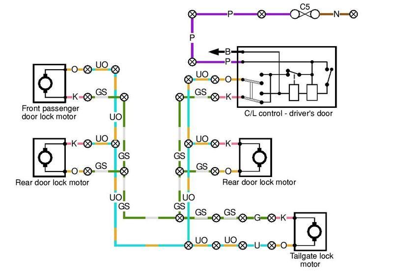
Here's the drawing I made of the SD1 central locking to give you an idea.
Posted: Tue May 09, 2017 5:02 pm
by scudderfish
And when you do wire it, only do one circuit at a time, and test it before moving on to the next. At regular intervals test previous circuits as well. You don't want to get to the end and then have to try and figure out why your hazards flash when you put it in reverse, but only when the alternator isn't charging.
Posted: Tue May 09, 2017 5:26 pm
by Ian Anderson
Posted: Tue May 09, 2017 6:42 pm
by ChrisJC
If you don't understand it, I would find a mate who you can bribe to help you do it. I have seen so many f*ckups by people who don't understand the basics, wire up a car, and it does all sorts of unreliable weird poop that makes them hate the car! And this is with a factory supplied loom that should be plug & play!
Chris.
Posted: Tue May 09, 2017 6:48 pm
by richardpope50
I did my own wiring and did it this way.
Sit in tintop and list all instruments, switches, etc. Decide what you will not need and add a few 12v outlets where you may not think you need them such as boot, dash, engine compartment For example, I needed an extra 12v for a twp speed rad fan. Add in 12v sockets for sat nav, etc.
Drawer by hand each circuit as Dave says above. Hand drawing is much easier. Draw each several times to get lines not crossing too much.
Drawing indicators / hazards and dim / dip / flash with fog light rules needs working out too.
Where circuits join each other, make a connector number.
Calculate fuse sizes based on amps. Get these from your tintop fuse list
Calculate amps for each circuit
Standardise on wire size. I did 10amp and 25 amp wiring. I chose to keep white 10 amp and red 25 amp with black earth but many will say choose colours.
make sure you have plenty of earth points. I used 6mm bolts rivnutted into my chassis for a good connection. DO NOT USE STAINLESS STEEL anywhere as I know to my cost. It creates a resistance and will burn out components.
In my case, I listed all circuits in a spreadsheet with amps and numbered each circuit in a series such as 1xx, 2xx, etc. Then I listed out each connection so, for example my LH indicator was 102 in front loom joining column loom connection 701.
You will need quite a lot of connectors / connections between looms so think this all out first. Don't use those 3M connector clips. I made a junction box where all looms connect with each other. Even then the back of the relay area is a real rat's nest but at least everything is numbered and I can easily trace any wire. Eg. Pin 86 of relay 5 goes to 207 which goes to 705.
If you want my spreadsheet with all my connections, PM me you e-mail address. I'll also scan a couple of my circuits, if you like.
HTH.
Posted: Wed May 10, 2017 7:11 am
by chodjinn
Awesome response guys thanks. I had considered the painless or similar kits Ian, but they're more designed for road going cars. Mine is not road legal / track only, so the majority of it I wouldn't use. I'm going to be running an FIA kill switch & push button start for ignition/starting and that's it - Can't find any wiring diagram to help with this apart from the FIA main connections.
I do have a friend who knows his stuff, can sort me a decent fuse/relay board for about £100 with 10 fuses, which should be enough I think. But any more than that an I will be paying him a fair wedge for his time.
I have two full, stripped car looms, so I have all the switches and connections and clips, plus a bunch of wire, that I should need hopefully!
The advice to do one circuit at a time is good, and drawing it out one at a time - I don't think I have an issue with that. It's the part of the loom between the battery/alternator/starter/ignition switch etc that I don't get, like what AMP breakers I should use between the battery and fuse board etc. Spent two hours reading last night, gave myself a headache haha!
Posted: Wed May 10, 2017 2:50 pm
by chodjinn
Can someone tell me how to upload a pdf file? I have drawn out the start of a basic wiring diagram and would appreciate some feedback if possible! cheers
Posted: Wed May 10, 2017 3:43 pm
by DaveEFI
chodjinn wrote:Can someone tell me how to upload a pdf file? I have drawn out the start of a basic wiring diagram and would appreciate some feedback if possible! cheers
Think you'll have to produce a JPEG from it and then use PhotoBucket etc in the normal way.
Posted: Thu May 11, 2017 9:40 pm
by stevieturbo
It would be easier either way to start with a base kit from Painless, or any of the US companies.
Even if you dont use it as is....it gives you a lot of wire and components to start with.
And road car or race car....it simply gives you circuits to use for whatever you want. Just because it's labelled lights...doesnt mean it has to be for lights for example.
Matt at DIYAutotune offers a load of MS wiring harnesses too and components
https://www.diyautotune.com/shop/wiring ... e-bundles/
CBS in the UK also offer various wire and components to start with.
http://www.carbuildersolutions.com/uk/f ... fuse-boxes
https://www.rbracing-rsr.com/wiring_ecu.html
Even Summit in the US offer their own kits too.
https://www.summitracing.com/int/search ... -harnesses
Only think with some of the US race harness kits...they'll have most of their relays triggered by a positive feed, which goes against what any ecu control will be doing. So if you do down that route you'll need to do a little re-wiring of the relay/fuse box itself to accommodate earth switching.
I had to do that with the 8 relay Painless kit I used for some of my stuff.
Posted: Fri May 12, 2017 5:55 am
by chodjinn
I already have the two large MS3 pro harnesses. Yeah I had considered those kits from a number of sources but I don't really see the point for me, at this moment. They're mainly just a fuse/relay board, and I already have that. The main part of the wiring that confuses me is the main engine/battery/starter/ignition part. Individual circuits/fuses aren't that bad I can get my head around those I hope!
I've spent the past two evenings stripping the two looms I had, so now I have a packing crate full of wiring to use, tons of spare relays/fuses/switches etc. I've managed to save a small Toyota fuse board/relay board so that should get me started at least.
I may, later down the line, buy a better board but as I don't know exactly what I need to do just now I'm gonna wait before spending any more money. I don't mind messign about and making mistakes with what I have at the moment as it didn't cost me owt! Righto, best get making some diagrams!
Posted: Fri May 12, 2017 7:35 am
by chodjinn
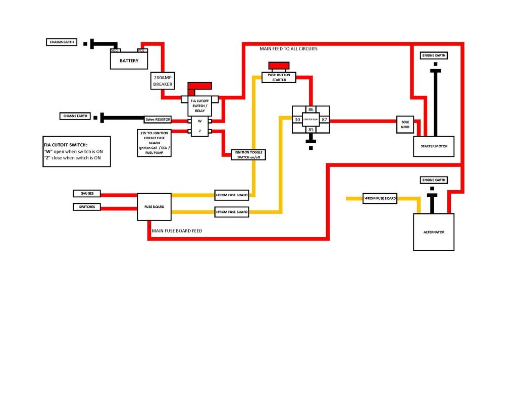
Righto, quiet morning at work has meant I have bashed my first attempt at a wiring diagram. This is for the main engine wiring loom, covering battery/alternator/starter, and the FIA kill switch.
I'm not running a key/barrel lock type ignition switch which is why I have drawn it the way I have, using an aircraft toggle switch/push button starter.
What do people think? I'm not sure about the 200amp breaker, or what fuses to use for the alternator/starter relay yet. What about a main fuse, where should it go / how big 75a, 120a etc?
Posted: Fri May 12, 2017 5:00 pm
by Ian Anderson
Race only car
Have a few kill switches or buttons on it running back to a relay breaker
Imagine if you end up upside down against a barrier unconscious and the only external cut off is near drivers side and that is buried in the dirt and Armco.
Said relay breaker should break noth positive and negative
Often if you only break one the engine will continue running.
Ian
Posted: Fri May 12, 2017 7:04 pm
by stevieturbo
If wired correctly, the kill switch will kill the engine too, and isolate/dump the alternator power to ground.
Pretty sure it must be wired into the positive feed for this to occur and done correctly.
Also some call it a kill switch, which makes sense. Although others call it a battery isolator switch...which can also make sense, but is a quite different function.
Posted: Sat May 13, 2017 8:17 am
by chodjinn
The kill switch kills everything, it's a proper FIA one not just a battery isolator. Have internal and external pull cords. Still havent a clue what i am doing, any suggestions if that diagram is ok? Or what's wrong with it? Thanks