
One tip as regards drawing things out is that for a schematic, you don't need to situate the components were they are. For example, you don't need to show all the fuses in one block - just because they are. They can be shown anywhere in that circuit.
You also need more wire colours. Each fused circuit would normally be different. Which also makes it easier to follow.
Time to start wiring the car!
Moderator: phpBB2 - Administrators
yeah I know, it's just how it turned out. I can change wire colours later, that's the least of my worries at the moment!DaveEFI wrote:One tip as regards drawing things out is that for a schematic, you don't need to situate the components were they are. For example, you don't need to show all the fuses in one block - just because they are. They can be shown anywhere in that circuit.
You also need more wire colours. Each fused circuit would normally be different. Which also makes it easier to follow.
RIP MGB V8 .... served me well as a learning curve.
R32 Skyline V8 .... this one is gonna be a monster!
R32 Skyline V8 .... this one is gonna be a monster!
-
stevieturbo
- Forum Contributor

- Posts: 3979
- Joined: Sat Nov 18, 2006 6:22 pm
- Location: Northern Ireland
For the most part, there isnt much wrong with the drawing other than the things I mentioned.chodjinn wrote:Yeah, didn't really understand most of that Stevie. The diagram was cobbled together with a little help from Rich. I'm still struggling to find any useful/consistent information. I would have thought there would be a lot out there for beginners but apparently not!
There is probably some software out there to assist with such drawings...but I'd be like you and MS Paint lol And you've done a better job than I ever would.
I'd have just used pen and paper.
So the 100a fuse for the alternator is ok?stevieturbo wrote:For the most part, there isnt much wrong with the drawing other than the things I mentioned.chodjinn wrote:Yeah, didn't really understand most of that Stevie. The diagram was cobbled together with a little help from Rich. I'm still struggling to find any useful/consistent information. I would have thought there would be a lot out there for beginners but apparently not!
There is probably some software out there to assist with such drawings...but I'd be like you and MS Paint lol And you've done a better job than I ever would.
I'd have just used pen and paper.
I can use a 300amp breaker after the battery, should be ok?
Not sure on the ignition/relay, as I said before I based it on a diagram rich sent me so I don't know what is the right way to do it. Same for the ECU signals, I understand what you are saying but not sure what it means in terms of how I wire/show it, if you know what I mean?
Also not sure on how to go about sizing fuses for things like fans, rear lights etc?
RIP MGB V8 .... served me well as a learning curve.
R32 Skyline V8 .... this one is gonna be a monster!
R32 Skyline V8 .... this one is gonna be a monster!
-
stevieturbo
- Forum Contributor
- Posts: 3979
- Joined: Sat Nov 18, 2006 6:22 pm
- Location: Northern Ireland
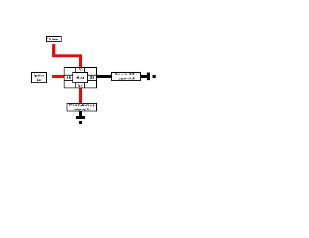
It simply means that the ecu provides the ground to trigger it. ie pin 85 on your drawing.
Pin 86 would just take a 12v, whether you make that permanent or via the ignition switch is up to you.
I tend to like adding a manual switch for this relay too...again to the pin 85 via ground in case you wanted to manually override the fan.
Pin 86 would just take a 12v, whether you make that permanent or via the ignition switch is up to you.
I tend to like adding a manual switch for this relay too...again to the pin 85 via ground in case you wanted to manually override the fan.
Y'see this is what I don't understand. I've taken that layout (for the Rad fan wiring let's say) as I found on google, and now you're saying it's completely wrong?stevieturbo wrote:It simply means that the ecu provides the ground to trigger it. ie pin 85 on your drawing.
Pin 86 would just take a 12v, whether you make that permanent or via the ignition switch is up to you.
I tend to like adding a manual switch for this relay too...again to the pin 85 via ground in case you wanted to manually override the fan.
The way I have/had it is the relay already gets 12v from the fuse board to pin 30? Can you show me what you mean because this is very confusing!
RIP MGB V8 .... served me well as a learning curve.
R32 Skyline V8 .... this one is gonna be a monster!
R32 Skyline V8 .... this one is gonna be a monster!
-
stevieturbo
- Forum Contributor
- Posts: 3979
- Joined: Sat Nov 18, 2006 6:22 pm
- Location: Northern Ireland
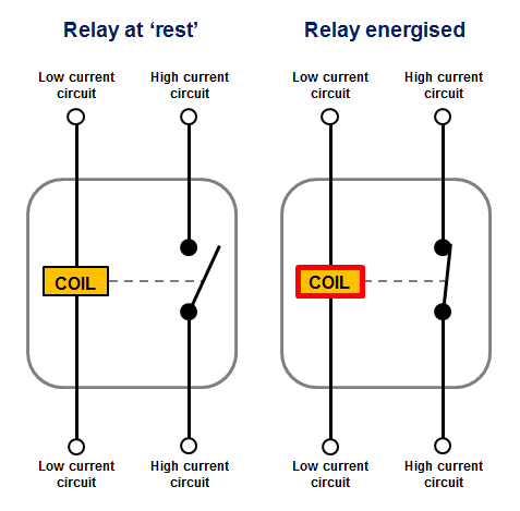
You're confusing the load side, with the trigger side.
A relay is simply a remote switch than turns a larger switch off/on so a small switch can handle large currents, or there is no actual physical switch. ie the ecu is turning it off or on, as per the fan.
For your fan you are showing a permanent ground to pin 85 and a "ecu signal" to pin 86 which on your drawing would need to be a 12v.
Virtually no ecu's I'm aware of send out 12v to trigger stuff like that. They almost all trigger via ground as you've shown for the heater relay.
Except the ecu provides the ground rather than a manual wiring or switch
-
stevieturbo
- Forum Contributor
- Posts: 3979
- Joined: Sat Nov 18, 2006 6:22 pm
- Location: Northern Ireland
Or with numbers.
30/87 dont really matter which way round they go but that is the line to supply the motor or whatever is the high current load.
85/86 whilst not polarity sensitive themselves, best to stick with convention as far as positive and negative go.
This is simply a low power 12v and ground to energise the coil and turn the relay on.
So you could switch either via 12v or ground just depends on your wiring etc. OEM's favour switching a lot of stuff like that via grounds, simply because it means less live wires flying about the place
 pic host
30/87 dont really matter which way round they go but that is the line to supply the motor or whatever is the high current load.
85/86 whilst not polarity sensitive themselves, best to stick with convention as far as positive and negative go.
This is simply a low power 12v and ground to energise the coil and turn the relay on.
So you could switch either via 12v or ground just depends on your wiring etc. OEM's favour switching a lot of stuff like that via grounds, simply because it means less live wires flying about the place
pic hostI'm ashamed to say I am still struggling with all this and not making any progress. I appreciate your comments Stevie I really do, but I just cannot get my head around it, there's different ways to do this and a lot of "you can do it like this, or like this, or like this but it depends on XX" so you can see why I am getting confused.
I produced a 'generic' relay wiring diagram, but I don't get the 12v constant/switched etc. or how they should be fused etc. You seem to suggest I need two separate power wires to 30 and 86 so is that 12v fused to 30 and 12v ignition to 86? If so can you explain what that means in relation to my main wiring loom, as it where do those feeds come from? 30 from the fuse board? 86 12v ignition from where?
I produced a 'generic' relay wiring diagram, but I don't get the 12v constant/switched etc. or how they should be fused etc. You seem to suggest I need two separate power wires to 30 and 86 so is that 12v fused to 30 and 12v ignition to 86? If so can you explain what that means in relation to my main wiring loom, as it where do those feeds come from? 30 from the fuse board? 86 12v ignition from where?
RIP MGB V8 .... served me well as a learning curve.
R32 Skyline V8 .... this one is gonna be a monster!
R32 Skyline V8 .... this one is gonna be a monster!
-
stevieturbo
- Forum Contributor
- Posts: 3979
- Joined: Sat Nov 18, 2006 6:22 pm
- Location: Northern Ireland
30 and 87 are purely to carry the heavy load going from the fuse to the device, motor, whatever.
86 is a very small wire purely to turn the relay off or on. Whether this comes from a physical switch to energise the relay via the live side, or as you have drawn it is a semi permanent live and the relay energised via ground/ecu is up to you.
This could be something you could energise any time....or this feed could via an ignition switch source so it could only ever energise the relay when the key is turned on ( I know you dont have a key...but you get the idea )
eg if it was a fuel pump, there would never be any need to have this wire live when the key is off.
If it was for a cooling fan, driver fan etc etc.....you may want to be able to turn these on at any time whether the engine is running, key is on, whatever.
In this case pin 86 would need to be live all the time, and you could energise the relay via a ground switch.
Obviously power source from 30 would also then need to be able to provide power at this time too.
So sometimes people will just tag in pin 86 and 30 together and everything is controlled via the ground pin 85.
-
stevieturbo
- Forum Contributor
- Posts: 3979
- Joined: Sat Nov 18, 2006 6:22 pm
- Location: Northern Ireland
Thanks stevie, as always. I have seen a few diagrams with 86 & 30 looped together and triggered from ground. This is what was getting me confused! Been doing other bits at the moment like fitting fuel lines and radiator lines to the rear (what a pain!) but hopefully be back on some serious wiring attempts this weekend!
RIP MGB V8 .... served me well as a learning curve.
R32 Skyline V8 .... this one is gonna be a monster!
R32 Skyline V8 .... this one is gonna be a monster!
-
unstable load
- Top Dog

- Posts: 1278
- Joined: Mon May 04, 2009 6:53 am
