
Starting to set up the Megasquirt. All wired in (more or less) but I'm getting a bad sync signal.
Trigger wheel set up as LS1
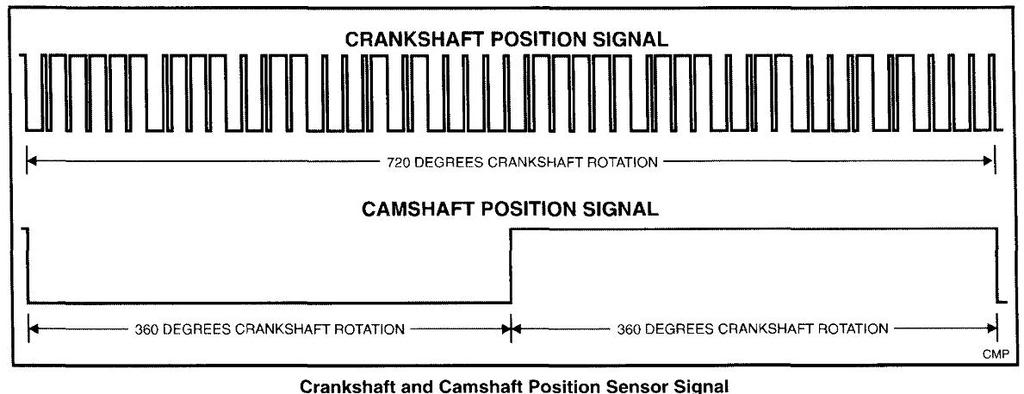
Crank signal looks generally good, but is 100% inverted in the composite logger.
Cam signal is all over the place.
Obviously the sync is all over the place too.
I have tried adjusting the cam sensor pots (R11 and R32) but that seems to have no effect. Not sure about this but there seems to be voltage on the cam signal wire coming from the ECU. I would have thought this would only see voltage when a signal is sent from the sensor...
Anybody have any clue where I can go next?
Rich.
Megasquirt help!!
Moderator: phpBB2 - Administrators
-
stevieturbo
- Forum Contributor

- Posts: 3979
- Joined: Sat Nov 18, 2006 6:22 pm
- Location: Northern Ireland
http://ls1tech.com/forums/conversions-h ... rough.html
Are you sure the ecu is set up for the 24x trigger setup and not the later 60-2 crank wheel ?
And when you say the signal is inverted, what do you mean ?
They use a hall sensor, so the signal can only either be 0v or 5v depending on whether a tooth is passing or not.
Likewise with cam.
Do you have any scope traces ?
D'oh, I thought I'd said that trivial piece of unnecessary info 
It's an MS3/MS3X from Phil at ExtraEFI.
I'm trying to run fully sequential. The engine is a GM Gen III L33 5.3, which should theoretically run as an LS1 as it's basically a 5.3 version of the LS1. It has the black 24x crank sensor and black 1x cam sensor.
Initially I couldn't get any signal from either cam or crank with the trigger wheel settings at LS1 in tunerstudio. I fiddled with the trigger wheel settings and found I could get some signal at "toothed wheel - 24", but it wasn't right and the number of missing teeth was set to 1 and greyed out, so I assumed I was getting some kind of signal and followed the instructions here and adjusted the R52 and R56 pots accordingly. I also checked against the cam settings at the time (further down that page) and found that Phil had jumped JP7 and the instructions said for LS1 to remove the jumper and set the R11 and R32 pots, so I tried that.
It now seems to see the crank signal in the comp log, but, as I said, the trace appears inverted when compared to the "baseline" signal.
When you look at this signal trace here and compare it to mine (https://onedrive.live.com/redir?resid=6 ... ile%2c.csv) (You'll have to copy and paste that url, Onedrive sucks at sharing stuff), the "pulses" are the right width, but sort of "upside down".
The cam signal, however, is all over the place. You can sort of see the basic shape, but it appears to be very noisy and, while I have fiddled with R11 a bit, this doesn't seem to have made any difference. Trouble is, I'm not sure what I should be adjusting and why, so I'm stumbling about in the dark a bit.
I don't have a scope either, just a multimeter.
-
stevieturbo
- Forum Contributor
- Posts: 3979
- Joined: Sat Nov 18, 2006 6:22 pm
- Location: Northern Ireland
Remove crank sensor and do a visual on the wheel.
I'd be surprised if it is 24x. Most newer stuff is 60-2, with a multitooth camwheel.
To verify either signal a scope is pretty essential if the ecu can't do it for you.
But visually check it first, it should be easy to see.
24x is just plain weird, 60-2 is a conventional multitooth wheel.
I'd be surprised if it is 24x. Most newer stuff is 60-2, with a multitooth camwheel.
To verify either signal a scope is pretty essential if the ecu can't do it for you.
But visually check it first, it should be easy to see.
24x is just plain weird, 60-2 is a conventional multitooth wheel.
I'm pretty sure it's 24x. It's from around 2004-2005. The L33 is a fairly rare engine in that gm only put them in certain vehicles for a couple of years before they changed to the gen IV engine.
It would be easy enough to see if the engine wasn't in the car, lol. However, from memory I'm pretty sure it had a black Crank sensor, also, the cam sensor is at the rear of the engine which is the correct place for the 24x setup. It was moved to the front for the 58x setup, from what I understand.
Rich
-
stevieturbo
- Forum Contributor
- Posts: 3979
- Joined: Sat Nov 18, 2006 6:22 pm
- Location: Northern Ireland
Is it a V3 (through hole components) or V3.57 (surface mount) main PCB?
However the early black 24x sensor needs 12v, the later 58X grey 5v, so I'd check you have the correct voltage there. There are hardware settings which are different between the two types as well.
If ok, set the crank sensor input:- (do this with the MS unplugged as some manage to short things with an ordinary screwdriver)
With a small screwdriver, turn the pots, R52 and R56, 7 turns anticlockwise (sometimes you may feel a "click" when the end position is reached, they can't be damaged by turning too far.)
Turn R56 about 2 turns clockwise.
Cam sensor input is the same except:-
Turn both pots (R11 and R32) 7 turns anticlockwise
Turn R11 about 3 turns clockwise.
Have you got a JimStim? It's so much easier to start out on the bench and get the basic settings there. With hall effect, it shouldn't need altering from the settings you get with the Jimstim - unlike a VR type.
I'm not well up on MS3 code - but there will be a setting to invert the signal?
Dave
London SW
Rover SD1 VDP EFI
MegaSquirt2 V3
EDIS8
Tech Edge 2Y
London SW
Rover SD1 VDP EFI
MegaSquirt2 V3
EDIS8
Tech Edge 2Y
The '24x' is the type of sensor. I asked as there are two different types used on the LS1stevieturbo wrote:Remove crank sensor and do a visual on the wheel.
I'd be surprised if it is 24x. Most newer stuff is 60-2, with a multitooth camwheel.
To verify either signal a scope is pretty essential if the ecu can't do it for you.
But visually check it first, it should be easy to see.
24x is just plain weird, 60-2 is a conventional multitooth wheel.
Dave
London SW
Rover SD1 VDP EFI
MegaSquirt2 V3
EDIS8
Tech Edge 2Y
London SW
Rover SD1 VDP EFI
MegaSquirt2 V3
EDIS8
Tech Edge 2Y
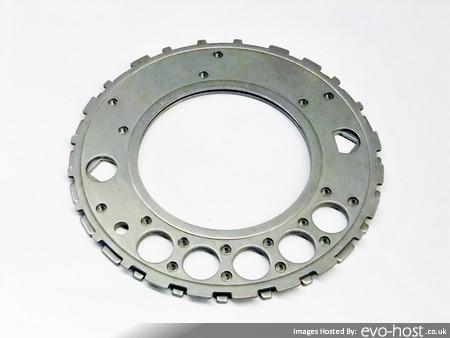
This is the same engine as I have, stripped down.
http://starcityracing.com/Forums/showthread.php?t=58345
Based on this link http://chevythunder.com/24x_and_58x_reluctors.jpg it looks like the 24x pattern to me.
Rich.
http://starcityracing.com/Forums/showthread.php?t=58345
Based on this link http://chevythunder.com/24x_and_58x_reluctors.jpg it looks like the 24x pattern to me.
Rich.
Dave,
it's a 3.0 board.
I have already done what you suggested regarding adjusting those pots.
I haven't got a Jimstim. I made the mistake of assuming the ms would be similar to something like an emerald, in that a pre built ecu for a specific engine wouldn't need me pulling it apart and fiddling with main board components, or plugging it into oscilloscopes and simulators before I even connect it to my engine.
-
stevieturbo
- Forum Contributor
- Posts: 3979
- Joined: Sat Nov 18, 2006 6:22 pm
- Location: Northern Ireland
24x refers to the trigger wheel. The 24x is a totally crap and weird wheel. 58x as they call it is a conventional 60-2 wheel that they give a stupid name.DaveEFI wrote:The '24x' is the type of sensor. I asked as there are two different types used on the LS1stevieturbo wrote:Remove crank sensor and do a visual on the wheel.
I'd be surprised if it is 24x. Most newer stuff is 60-2, with a multitooth camwheel.
To verify either signal a scope is pretty essential if the ecu can't do it for you.
But visually check it first, it should be easy to see.
24x is just plain weird, 60-2 is a conventional multitooth wheel.
They also use different sensors, again because the 24x is a stupid design with 2 tracks instead of a single big tooth
-
stevieturbo
- Forum Contributor
- Posts: 3979
- Joined: Sat Nov 18, 2006 6:22 pm
- Location: Northern Ireland
Right. MS 2 can use either, but for wasted spark only. So can obviously cope with either trigger wheel - you just ignore the cam sensor.stevieturbo wrote:24x refers to the trigger wheel. The 24x is a totally crap and weird wheel. 58x as they call it is a conventional 60-2 wheel that they give a stupid name.DaveEFI wrote:The '24x' is the type of sensor. I asked as there are two different types used on the LS1stevieturbo wrote:Remove crank sensor and do a visual on the wheel.
I'd be surprised if it is 24x. Most newer stuff is 60-2, with a multitooth camwheel.
To verify either signal a scope is pretty essential if the ecu can't do it for you.
But visually check it first, it should be easy to see.
24x is just plain weird, 60-2 is a conventional multitooth wheel.
They also use different sensors, again because the 24x is a stupid design with 2 tracks instead of a single big tooth
I dunno much about MS3, but it suggests it can do sequential with either too, as it's covered in the manual.
Dave
London SW
Rover SD1 VDP EFI
MegaSquirt2 V3
EDIS8
Tech Edge 2Y
London SW
Rover SD1 VDP EFI
MegaSquirt2 V3
EDIS8
Tech Edge 2Y
